CyberPower Smart App Sinewave Series, PR500LCDRT1U, PR750LCDRT1U, PR1000LCDRT1U Manual
- User manual (2 pages) ,
- User manual (2 pages) ,
- User manual (2 pages)
Advertisement
- 1 IMPORTANT SAFETY WARNINGS
- 2 INSTALLING YOUR PRODUCT
- 3 FRONT/REAR PANEL DESCRIPTION
- 4 BATTERY REPLACEMENT
- 5 LCD STATUS DEFINITION
- 6 LCD SETUP FUCTIONS
- 7 TROUBLE SHOOTING
- 8 TECHNICAL SPECIFICATIONS
- 9 ENERGY-SAVING TECHNOLOGY
- 10 LIMITED WARRANTY AND CONNECTED EQUIPMENT GUARANTEE
- 11 Documents / Resources
IMPORTANT SAFETY WARNINGS
This manual contains important instructions that should be followed during installation and maintenance of the UPS and batteries. Please read and follow all instructions carefully during installation and operation of the unit. Read this manual thoroughly before attempting to unpack, install, or operate.

The UPS must be connected to a grounded AC power outlet with fuse or circuit breaker protection. DO NOT plug the UPS into an outlet that is not grounded. If you need to de-energize this equipment, turn off and unplug the UPS.
DO NOT USE FOR MEDICAL OR LIFE SUPPORT EQUIPMENT! CyberPower Systems does not sell products for life support or medical applications. DO NOT use in any circumstance that would affect operation or safety of any life support equipment, with any medical applications, or patient care.
The battery can energize hazardous live parts inside even when the AC input power is disconnected.
For pluggable equipment, the socket-outlet shall be installed near the equipment and shall be easily accessible.


To prevent the risk of fire or electric shock, install in a temperature and humidity controlled indoor area, free of conductive contaminants. Please see specifications for acceptable temperature and humidity range.
To reduce the risk of electric shock, do not remove the cover, except to service the battery. There are no serviceable parts inside, except for the battery.
To avoid electrical shock, turn off the unit and unplug it from the AC power source before servicing the battery or installing a computer component.
DO NOT USE WITH OR NEAR AQUARIUMS! To reduce the risk of fire, do not use with or near aquariums. Condensation from the aquarium can come in contact with metal electrical contacts and cause the machine to short out.
DO NOT USE WITH LASER PRINTERS! The power demands of laser printers are too large for a UPS.
INSTALLING YOUR PRODUCT
UNPACKING
Inspect the UPS upon receipt. The box should contain the following.
(1) UPS Unit; (1) User's Manual for UPS; (2) Rack Mount Brackets; (2) Wall Mount Brackets; (2) Stands (1) Emergency Power Off Cable (gray) (1) PowerPanel Business Edition Software CD; (1) Serial Interface Cable (RJ45/DB-9); (1) USB A+B type cable; (1) Warranty Registration Card.
OVERVIEW
The PR500LCDRT1U/PR750LCDRT1U/PR1000LCDRT1U provides automatic voltage regulation for inconsistent utility power. The PR500LCDRT1U/PR750LCDRT1U/PR1000LCDRT1U features 1030 Joules of surge protection, and provides battery backup during power outages. The PR500LCDRT1U/PR750LCDRT1U/PR1000LCDRT1U ensures consistent power to your computer system and its included software will automatically save your open files and shutdown your computer system during a utility power loss.
AUTOMATIC VOLTAGE REGULATOR
The PR500LCDRT1U/PR750LCDRT1U/PR1000LCDRT1U stabilizes inconsistent utility power. The incoming utility power may be damaging to important data and hardware, but with Automatic Voltage Regulation, the computer will not experience damaging voltage levels. An Automatic Voltage Regulator automatically increases low or decreases high voltage to a consistent, computer safe 110/120V. The unit powerful sealed lead-acid batteries will provide power only if the incoming voltage drops below 80v or increases above 150V.

SYSTEM BLOCK DIAGRAM

HARDWARE INSTALLATION GUIDE
- Your new UPS may be used immediately upon receipt. However, recharging the battery for at least four hours is recommended to ensure that the battery's maximum charge capacity is achieved. Charge loss may occur during shipping and storage. To recharge the battery, simply leave the unit plugged into an AC outlet. The unit will charge in both the on and off position.

When you first receive the unit, plug in the unit to fully charge the battery.
- If you will use the software, connect the serial interface cable to the serial port on the UPS and the computer. If you would like to use USB cable, please connect the USB cable on the UPS then connect the USB cable to your computer.
- With the UPS unit off and unplugged, connect your computer, monitor, and any externally powered data storage device (Hard drive, Tape drive, etc.) into the battery power supplied outlets. DO NOT plug a laser printer, copier, space heater, vacuum, paper shredder or other large electrical device into the UPS. The power demands of these devices will overload and possibly damage the unit.

Unplug the unit and turn Power Off when first connecting your computer and peripherals.
- Plug the UPS into a 2 pole, 3 wire grounded receptacle (wall outlet). Make sure the wall branch outlet is protected by a fuse or circuit breaker and does not service equipment with large electrical demands (e.g. air conditioner, refrigerator, copier, etc.). Avoid using extension cords.
![]()
- Depress the power switch to turn the unit on. The power on indicator light will illuminate. If an overload is detected, an audible alarm will sound and the unit will emit one long beep. To correct this, turn the UPS off and unplug at least one piece of equipment from the battery power supplied outlets. Wait 10 seconds. Make sure the circuit breaker is depressed and then turn the UPS on.
- To maintain optimal battery charge, leave the UPS plugged into an AC outlet at all times.
- To store your UPS for an extended period, cover it and store with the battery fully charged. Recharge the battery every three months to ensure battery life.
- Professional Rack Mount UPS provides one RJ45 and one USB port to allow connection and communication between the UPS and computers or equipment. The Primary computers (with PowerPanel Business Edition installed) are the computers that you will use to control the UPS and make any changes to the operation of the UPS. When there is a power failure, the computer which connects to Primary port will start to shutdown after a user controlled delay. PowerPanel Business Edition will save and close any open files prior to shutting the system down.
- EPO (Emergency Power Off) Port:
The feature is for the application to enable emergency power shutdown. Use the gray cable provided to connect the UPS to a normally closed or normally open contact switch according to the circuit diagram. EPO function is provided in the UPS. EPO remote switch which is a Push-Back button installed computer room outside by a phone line and not connected any other equipment.


*Note: Both USB and Serial can not be used simultaneously.

Install PowerPanel Business Edition software on the primary computer connected to UPS with either a serial cable or USB cable.
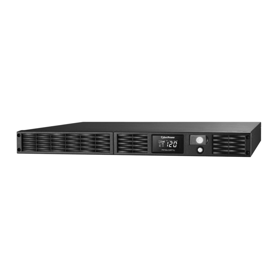
FRONT/REAR PANEL DESCRIPTION

- Power Switch
Master on/off switch for equipment connected to the UPS. - Power On Indicator
Indicates the power is on. - LCD Module Display
LCD shows all the UPS information with icons and messages. - LCD Display Toggle Button
The button can be used to toggle between different data displays on the LCD. - Battery Backup and Surge Protected Outlets
Provides six battery powered, surge protected and AVR outlets for connected equipment and ensures temporary uninterrupted operation of connected equipment during a power failure.
Surge Only
Surge only outlet provide surge protection without backup and AVR function.
Critical/Non-critical
When the UPS is overloaded, the circuit breakers will be tripped to interrupt the power supply to the uncritical outlets while continuing to supply the critical outlets. As well, as the battery capacity depletes under the threshold value, the uncritical outlets will be shut down and provide energy for critical outlets. The threshold can be determined and set by users. Non-critical outlets can also be turned on/off manually through the software package provided. - Input Power Cord
Heavy-duty, extra long power cord. - Input Circuit Breaker
Resettable circuit breakers provide Input optimal overload Protection. - USB port
USB communication port for management software. - Serial Port
Serial port allows connection and communication between the UPS and the computer. - SNMP/HTTP Network slot
Remove the cover panel to install optional RMCARD that allows remote monitoring and control UPS on networks. - Site Wire Fault Indicator
This LED will illuminate to warn the user that a wiring problem exists within the AC receptacle, such as a bad ground, missing ground or reversed wiring. If illuminated, disconnect all equipment and contact an electrician to ensure outlet is properly wired. - EPO (Emergency Power Off) port
The interface can be used to connect to switches for emergency power off.
BATTERY REPLACEMENT
Contact your dealer, or email tech@cpsww.com. Refer to replacement battery pack number RBP292 for PR500LCDRT1U, RBP472 for PR750LCDRT1U and RBP492 for PR1000LCDRT1U.
Read and follow the IMPORTANT SAFETY INSTRUCTIONS before servicing the battery. Service the battery under the supervision of personnel knowledgeable of batteries and their precautions. Servicing the battery should only be performed by trained personnel.
Replacement of batteries located in an OPERATOR ACCESS AREA.
When replacing batteries, replace with the same number of the following battery: HR9-6FR(BB) for PR500LCDRT1U and PR1000LCDRT1U, BP7-6FR(BB) for PR750LCDRT1U.

Risk of Energy Hazard, 6V, maximum 9 Ampere-hour batteries. Before replacing batteries, remove conductive jewelry such as chains, wrist watches, and rings. High energy through conductive materials could cause severe burns.
Risk of battery explosion, if battery is replaced by an incorrect type. Dispose of used battery according to the instructions.
To reduce the risk of fire, connect only to a circuit provided with 20 amperes maximum branch circuit overcurrent protection in accordance with the National Electric Code, ANSI/NFPA 70.
Use only the specified type of battery. See your dealer for replacement batteries.
The battery may present the risk of electrical shock. Do not dispose of batteries in a fire, as they may explode. Follow all local ordinances regarding proper disposal of batteries.
Do not open or mutilate the batteries. Release electrolyte is harmful to the skin and eyes and may be toxic.
A battery can present a high risk of short circuit current and electrical shock.
Take the following precautions before replacing the battery:
- Remove all watches, rings or other metal objects.
- Only use tools with insulated handles.
- Do not lay tools or metal parts on top of battery or any terminals.
- Wear rubber gloves and boots.
![shock hazard]() Determine if the battery is inadvertently grounded. If inadvertently grounded, remove source of ground.CONTACT WITH A GROUNDED BATTERY CAN RESULT IN ELECTRICAL SHOCK! The likelihood of such shock will be reduced if such grounds are removed during installation and maintenance (applicable to a UPS and a remote battery supply not having a grounded circuit)
Determine if the battery is inadvertently grounded. If inadvertently grounded, remove source of ground.CONTACT WITH A GROUNDED BATTERY CAN RESULT IN ELECTRICAL SHOCK! The likelihood of such shock will be reduced if such grounds are removed during installation and maintenance (applicable to a UPS and a remote battery supply not having a grounded circuit)
 Determine if the battery is inadvertently grounded. If inadvertently grounded, remove source of ground.CONTACT WITH A GROUNDED BATTERY CAN RESULT IN ELECTRICAL SHOCK! The likelihood of such shock will be reduced if such grounds are removed during installation and maintenance (applicable to a UPS and a remote battery supply not having a grounded circuit)
BATTERY REPLACEMENT PROCEDURE:
- Remove two screws and right side front panel.
![]()
- Disconnect the black and red cable.

- Remove two retaining screws and pull out battery cabin.
![]()


LCD STATUS DEFINITION

"V" illuminated, "X" Not illuminated, "— " either
LCD SETUP FUCTIONS
Set-up Mode
- The machine enters Set-Up Mode after holding the Display toggle for 10 seconds.
- By pressing the Display toggle, users can switch between setup functions. User configurable functions are as follows:
- Sensitivity: Set the level of tolerance for UPS. Increase the UPS compatibility for local utility power condition.
High: The UPS will turn to battery power more often to provide the steady power supply to the connected equipment.
Low: The UPS will tolerate more fluctuations and turn to battery power less often. - Battery Lifetime: Show the batteries already used time. Reset the logger when battery module replacement or first time installation.
- Firmware Version: Show the UPS version number.
- Sensitivity: Set the level of tolerance for UPS. Increase the UPS compatibility for local utility power condition.
The settable items are sorted by unit as in the following table:
| Items | Unit | |
| 1 | Sensitivity | |
| 2 | Battery Lifetime | Year |
| 3 | Firmware Version |
- Press and hold the toggle for 4 seconds. When the icons blink, the value of each item can be changed by slightly pressing the toggle.
- To save the value and return to general mode, press and hold the toggle for 4 seconds.
Note: If the machine is left idle for over 30 seconds during setup, it will turn off the backlight and return to general mode automatically.
Note: If user wants to return to general mode without saving changes, there are two methods:
- Wait for the backlight to turn off
- Press and hold the "Display" toggle for 10 seconds
TROUBLE SHOOTING
| Problem | Possible Cause | Solution |
Outlet do not provide power to equipment | Circuit breaker has tripped due to an overload. | Turn the UPS off and unplug at least one piece of equipment. Wait 10 seconds, reset the circuit breaker by depressing the button, and then turn the UPS on. |
| Batteries are discharged | Recharge the unit for at least 4 hours | |
| Unit has been damaged by a surge or spike. | Contact CyberPower Systems about replacement batteries at tech@cpsww.com | |
| Uncritical outlets have turned off automatically due to an overload | Push the toggle button to make the uncritical outlets turn on. | |
The device does not perform expected runtime | Battery not fully charged. | Recharge the battery by leaving the UPS plugged in. |
| Battery is degraded | Contact CyberPower Systems about replacement batteries at tech@cpsww.com | |
The device will not turn on | The on/off switch is designed to prevent damage by rapidly turning it off and on. | Turn the UPS off. Wait 10 seconds and then turn the UPS on. |
| The unit is not connected to an AC outlet. | The unit must be connected to a 110/120v outlet. | |
| The battery is worn out. | Contact CyberPower Systems about replacement batteries at tech@cpsww.com | |
| Mechanical problem. | Contact CyberPower Systems at tech@cpsww.com | |
PowerPanel Personal Edition is inactive | The serial cable or USB cable is not connected. | Connect the cable to the UPS unit. You must use the cable that came with the unit. |
| The cable is connected to the wrong port. | Try another port of your computer | |
| The unit is not providing battery power. | Shutdown your computer and turn the UPS off. Wait 10 seconds and turn the UPS back on. This should reset the unit. | |
| The serial cable is not the cable that was provided with the unit. | You must use the cable included with the unit for the software |
Additional troubleshooting information can be found at www.cyberpowersystems.com/support.htm
TECHNICAL SPECIFICATIONS
| Model | PR500LCDRT1U | PR750LCDRT1U | PR1000LCDRT1U |
| Capacity(VA) | 500 | 750 | 1000 |
| Capacity(Watts) | 400 | 600 | 800 |
| Input | |||
| Input Plug Type | NEMA 5-15P | ||
| Input Voltage Range | 80Vac-150Vac | ||
| Input Frequency Range | 60Hz+/-3Hz(auto sensing) | ||
| Output | |||
| On Battery Output Voltage | Pure Sine Wave at 120Vac+/-5% | ||
| On Battery Output Frequency | 60Hz+/-1% | ||
| Transfer Time(Typical) | 4 ms | ||
| Overload Protection | On Utility: Circuit Breaker, On Battery: Internal Current Limiting | ||
| Surge Protection and Filtering | |||
| Lightning/Surge Protection | Yes | ||
| Physical | |||
| Output Receptacles | (6)NEMA 5-15R+(1)NEMA 5-15R Surge Only | ||
| Dimensions(in) | 1U Rack, 17.25'' x 9.1'' x 1.75'' | 1U Rack, 17.25'' x 16.8'' x 1.75'' | |
| Weight (lb) | 19.8 | 30.7 | 35.9 |
| Battery | |||
| Runtime(Min) | 3 | 3 | 3.5 |
| Charger(A) | 0.8 | 0.7 | 0.8 |
| Sealed Maintenance Free Lead Acid Battery | 6V / 9.0AHx2 | 6V / 7.0AHx4 | 6V / 9.0AHx4 |
| Hot Swappable Battery | Yes | ||
| Warning Diagnostics | |||
| Indicators | Power On, Wiring Fault, LCD Display (Using Battery, AVR, Load Level, Battery Level) | ||
| Audible Alarms | On Battery, Low Battery, Overload | ||
| Environmental | |||
| Operating Temperature | 32°F to 104°F ( 0°C to 40°C ) | ||
| Operating Relative Humidity | 0 to 95% Non-Condensing | ||
| Operating Elevation | 0-10000 feet (0-3000 meters) | ||
| Communication | |||
| PowerPanel Business Edition | Windows 98/ME/NT/2000/XP/Vista/7 | ||
| Management | |||
| Self-Test | Manual Self-Test | ||
| Auto-Charger/ Auto-Restart | Yes | ||
| COM Interface | True RS232 x1 | ||
| Built-in USB Interface | Yes | ||
| SNMP/ HTTP Network Slot | Yes | ||
| Safety Approvals | UL1778,cUL107,FCC Part 15 Class A,CSA | ||
ENERGY-SAVING TECHNOLOGY
GreenPower UPS
The CyberPower GreenPower UPS cuts UPS energy costs by up to 75% compared to the conventional UPS circuits. Conventional UPS systems pass power through a transformer to provide normal output voltage to protected devices. By contrast, the GreenPower UPS circuitry bypasses the transformer when utility power is normal, significantly increasing the power efficiency of the UPS. As a result, a GreenPower UPS produces less heat and uses less energy reducing energy costs.
When utility power is abnormal, the GreenPower UPS operates like a normal UPS. Since utility power operates normally 88% of the time, the GreenPower UPS operates primarily in its cost-cutting bypass mode.
LIMITED WARRANTY AND CONNECTED EQUIPMENT GUARANTEE
How Do You Get Service?
- Call us at (877) 297-6937 or write to us at Cyber Power Systems (USA), Inc., 4241 12th Ave. E., STE 400, Shakopee, MN 55379 or send us an e-mail message at claims@cpsww.com for instructions.
- When you contact CyberPower, identify the Product, the Purchase Date, and the item(s) of Connected Equipment. Have information on all applicable insurance or other resources of recovery/payment that are available to the Initial Customer and Request a Claim Number.
For further information please feel free to contact CyberPower at Cyber Power Systems (USA), Inc. 4241 12th Ave E., STE 400, Shakopee, MN 55379; call us at (877) 297-6937; or send us an e-mail message at claims@cpsww.com.
Documents / ResourcesDownload manual
Here you can download full pdf version of manual, it may contain additional safety instructions, warranty information, FCC rules, etc.
Download CyberPower Smart App Sinewave Series, PR500LCDRT1U, PR750LCDRT1U, PR1000LCDRT1U Manual
Advertisement


Need help?
Do you have a question about the Smart App Sinewave Series and is the answer not in the manual?
Questions and answers