User Manuals: CyberPower SM040KAMFA 3-Phase Modular UPS
Manuals and User Guides for CyberPower SM040KAMFA 3-Phase Modular UPS. We have 2 CyberPower SM040KAMFA 3-Phase Modular UPS manuals available for free PDF download: Installation Manual, Operator's Manual

CyberPower SM040KAMFA Installation Manual (129 pages)
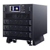
SMART APP ONLINE MODULAR 3-PHASE UPS SYSTEM
Brand: CyberPower
|
Category: UPS
|
Size: 6 MB
Table of Contents
Advertisement
CyberPower SM040KAMFA Operator's Manual (57 pages)
SMART APP ONLINE MODULAR 3-PHASE UPS SYSTEM
Brand: CyberPower
|
Category: UPS
|
Size: 3 MB