Table of Contents
Advertisement
Available languages
Available languages
Quick Links
Advertisement
Table of Contents

Related Manuals for Eaton 738r


Summary of Contents for Eaton 738r
- Page 1 738r Issue 2...
- Page 2 This product complies with the requirements of European Directive: 1995/5/EC (Radio &Telecommunications Terminal Equipment Directive). Ce produit est conforme aux exigences de la directive européenne : 1995/5/EC (Equipements terminaux de radio et de télécommunication). Dit product is conform de normen van de Europese Richtlijn 1995/5/EC (R&TTE Richtlijn) Questo prodotto è...
-
Page 3: Technical Specification
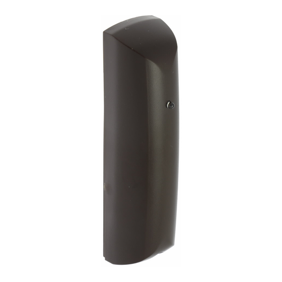
Introduction The 738r Radio Spyder is a vibration and shock sensor capable of transmitting alarm infor- mation using Eaton’s Security Business’s 868MHz narrow band technology. The 738r can report to any compatible Eaton’s Security Business receiver. The receivers can learn the unique identity of each 738r through either an infra-red LED or radio transmissions. - Page 4 Figure 1 shows the external appearance and internal layout of the 738r. Figure 2 shows the indicators and controls on the 738r’s printed circuit board. 1. Activity LED 2. Cover screw 3. Aerial 4. Transmitter module 5. Battery Fig. 1...
- Page 5 1. Activity/Learn LED 2. VR1. Sensitivity potentiometer 3. Lid tamper switch 4. Calibration LED 5. Battery 6. Back tamper switch 7. Mode jumpers Fig. 2...
-
Page 6: Compatible Equipment
Next to electronic equipment, particularly computers, photocopiers or other radio equipment. Upside down. Figures 3 and 4 show further considerations when using the 738r as a shock sensor to monitor, for example, windows. Do NOT mount the unit on moving panels. - Page 7 Fig. 3 Fig. 4 Note: Range shown for guidance only. Sensitivity may vary on different surfaces.
-
Page 8: Preparing For Installation
Preparing for Installation 1. Open the case by removing the cover screw and pivoting the cover up from the bottom. 2. Remove the PCB by sliding the PCB up out of the PCB brackets. 3. Install one 3V CR2 Li/MnO2 battery (supplied) in the battery holder on the PCB. Learning 1. - Page 9 Fit jumper C in order to adjust the sensitivity or confirm correct operation. Remove jumper C to put the 738r into normal operation. Note that the 738r can only enter calibration mode when the lid tamper switch is open. (See “To Commission the 738r”...
- Page 10 Fig. 5 Fig. 6 Fig. 8 Fig. 7...
- Page 11 To commission the 738r: 1. Fit jumper C and A to put the 738r into calibration mode at low sensitivity (see Fig 8). Note: If the battery is low then the Calibration LED flashes continuously. Fit a new battery.
- Page 12 5. Remove the sensitivity link (jumper A) if the sensor is unable to detect shocks from the whole of the area you wish to guard. 6. Remove the calibration link (jumper C) once you have achieved the desired sensitivity. This places the 738r in its normal operating mode.
-
Page 13: Maintenance
Change the battery every 24 months, or when the control unit indicates low detector bat- tery. The 738r indicates low battery by sending a message to the receiver. In addition, the Activ- ity LED will not operate if the battery is low (even if jumper D is removed). - Page 14 Every effort has been made to ensure that the contents of this leaflet are correct . How- ever, neither the authors nor Eaton’s Security Business accept any liability for loss or dam- age caused or alleged to be caused directly or indirectly by this leaflet. The contents of this leaflet are subject to change without notice.
-
Page 15: Technische Specificaties
Introductie De draadloze Spyder 738r is een trilling- en schokdetector die de alarminformatie via de 868MHz smalband technologie van Eaton’s Security Business kan verzenden. De draadloze Spyder kan naar elke 7xx ontvanger, of 9960 draadloze uitbreiding, of naar de Homelink 75 van Eaton’s Security Business rapporteren. De ontvangers kunnen de unieke identiteit van elke Spyder leren door middel van een infrarood LED of draadloze data overdracht. - Page 16 Afbeelding 1 toont het uiterlijk van de Spyder. Afbeelding 2 toont de LED’s en de regelaars op het PCB van de Spyder. 1. Activiteiten-LED 2. Bevestigingsschroef 3. Antenne 4. Zendmodule 5. Batterij Fig. 1...
- Page 17 1. Activiteiten-/Leer-LED 2. VR1. Gevoeligheidspotentiometer 3. Sabotageschakelaar deksel 4. Calibratie-LED 5. Batterij 6. Sabotageschakelaar rug 7. Brugschakelaars Fig. 2...
- Page 18 Naast elektronische apparatuur met name computers, kopieerapparaten of andere draadloze apparatuur. Ondersteboven. De afbeeldingen 3 en 4 tonen aanvullende voorwaarden als u de 738r als een schokdetec- tor gebruikt om, bijvoorbeeld, ramen te bewaken. Monteer de detector niet op bewegende panelen.
- Page 19 Fig. 3 Fig. 4 Opm.: Het getoonde bereik is een indicatie. De gevoeligheid is afhankelijk van de om- standigheden.
- Page 20 2. Schuif de pcb uit de houders en neem de pcb uit de behuizing. 3. Plaats een 3V CR2 Li/MnO2 batterij (bijgeleverd) in de batterijhouder op de pcb. Zo leert de ontvanger de 738r herkennen 1. Voordat u begint zet u eerst de ontvanger in de ‘leer’- stand (raadpleeg de handleiding van de ontvanger).
- Page 21 U kunt de Spyder alleen in de calibratie-stand zetten als de sabotageschakelaar van het deksel open staat. Zie hieronder “Zo regelt u de 738r af”. Discreet Plaats brug D op de pennen om de activiteiten-LED uit te schakelen. Neem de...
- Page 22 Fig. 5 Fig. 6 Fig. 8 Fig. 7...
- Page 23 B: Van de pennen (geen bewaking), C: Van de pennen (normaal gebruik), D: Van de pennen (LED ingeschakeld). Zo regelt u de 738r af: 1. Plaats brug C op de pennen waardoor u de Spyder in de calibratie-stand zet.
- Page 24 Vervang de batterij om de 24 maanden, of wanneer het controlepaneel een batterij-laag melding geeft. De 738r geeft een zwakke batterij aan met een batterij-laag melding naar het con- trolepaneel. Bovendien zal bij een zwakke batterij de activiteiten-LED niet functioneren (vooropgesteld dat brug D niet op de pennen is geplaatst).
-
Page 25: Spécifications Techniques
Introduction Le détecteur radio Spyder 738r est un détecteur de chocs et de vibrations capable de transmettre des informations d’alarme en utilisant la technologie de bande passante étroite 868 MHz propre à Eaton’s Security Business. Il est ainsi en mesure de transmettre des données à... - Page 26 Autoprotections Avant et arrière Dimensions 112 x 30 x 27 mm (h x l x p) Poids 46 g (pile incluse) Conformité EN50131-2 Niveau 2 EN61000-6-3:2001 Norme environnementale classe II La figure 1 montre comment se présente l’extérieur du détecteur Spyder. La figure 2 présente quant à...
- Page 27 1. LED d’activité / d’apprentissage 2. Potentiomètre de réglage de la sensibilité VR1 3. Contact d’autoprotection d’ouverture du boîtier 4. LED Calibrage 5. Pile 6. Contact d’autoprotection à l’arrachage 7. Cavaliers de sélection des modes de fonctionne- ment Fig. 2...
- Page 28 A l’envers. Les figures 3 et 4 donnent des informations complémentaires qu’il peut être utile de con- naître si le 738r est utilisé comme détecteur de chocs devant superviser des fenêtres (par exemple). Le détecteur NE DOIT PAS être installé sur des parties mobiles.
- Page 29 par plusieurs détecteurs, il est impératif de s’assurer que ceux-ci ne sont pas espacés de plus de 10 mètres les uns des autres. Dans le cas contraire, toute la surface peut ne pas être incluse dans la surveillance. Fig. 3 Fig.
-
Page 30: Préparation De L'installation
Préparation de l’installation 1. Retirer la vis du capot puis soulever ce dernier. 2. Extraire le circuit imprimé en le faisant glisser hors de son support de fixation. 3. Installer une pile 3 V CR2 Li/MnO2 (fournie) dans l’emplacement prévu à cet effet sur le circuit imprimé. - Page 31 fisamment la barre d’autoprotection se trouvant à l’intérieur du boîtier pour permettre l’activation du contact d’autoprotection. 5. Remettre le circuit imprimé à sa place, dans l’embase du boîtier. Configuration Le détecteur radio Spyder peut prendre plusieurs modes de fonctionnement. La sélection du mode de fonctionnement requis se fait en positionnant les cavaliers comme suit : Cavalier Fonction...
- Page 32 radio Spyder. Il est à noter que ce détecteur ne peut être placé en mode Calibrage que lorsque le contact d’autoprotection d’ouverture du capot est ouvert (voir le paragraphe “Mise en service du détecteur radio Spyder” ci-dessous.) Mode Discret Maintenir le cavalier D en place pour désactiver le fonctionnement de la LED d’activité.
- Page 33 Fig. 5 Fig. 6 Fig. 8 Fig. 7...
- Page 34 Mise en service du détecteur radio Spyder : 1. Mettre le cavalier C en place afin de faire passer le détecteur radio Spyder en mode calibrage. Remarque : si la tension de la pile est faible, la LED Calibrage clignote en continu. Il est dans ce cas nécessaire de remplacer la pile.
- Page 35 Le détecteur 738r signale que la tension de sa pile est faible en envoyant un message cor- respondant à la centrale d’alarme. Il est de plus à noter que la LED d’activité ne fonctionne pas lorsque la tension de la pile est basse (pour autant que le cavalier D ne soit pas en place).
- Page 36 La plus grande attention a été apportée à l’exactitude des informations contenues dans ce document. Les auteurs de cette notice ainsi que la société Eaton’s Security Business déclinent toute responsabilité en cas de pertes ou de dommages provoqués ou supposés avoir été...
-
Page 37: Specifiche Tecniche
868MHz, FM e Banda Stretta per trasmettere gli allarmi. Il sensore è compatibile con i ricevitori 762 e 768, espansioni 9960 e la centrale Homelink 75. Il 738r è, infatti, in grado di trasmettere il proprio codice ID via infrarosso emesso dal LED di attività e via radio. - Page 38 1. LED Attività 2. Vite coperchio 3. Antenna 4. Modulo trasmettitore 5. Batteria Fig. 1...
- Page 39 1. LED Attività/Apprendimento 2. VR1. Potenziometro per la sensibilità 3. Tamper coperchio 4. LED calibrazione 5. Batteria 6. Tamper posteriore antistrappo 7. Jumper per modo di funzionamento Fig. 2...
-
Page 40: Dispositivi Compatibili
Vicino a dispositivi elettronici quali computer, fotocopiatrici, congelatori o altri dispositivi radio. Sottosopra. Le Figure 3 e 4 mostrano ulteriori considerazioni sull’utilizzo del sensore 738r per la pro- tezione delle finestre. NON installare l’unità sulla parte in movimento della finestra. - Page 41 Fig. 3 Fig. 4 Nota: La copertura mostrata è solo di esem- pio. La sensibilità può variare a seconda della superficie..
- Page 42 Preparazione alla Installazione 1. Rimuovere le viti ed aprire il contenitore dal basso. 2. Liberare il circuito stampato dagli appositi sostegni per rimuoverlo. 3. Inserire la batteria in dotazione (3V CR2 Li/MnO2) nell’apposto alloggiamento. Apprendimento 1. Assicurarsi che il ricevitore sia in apprendimento (vedere il manuale di programmazione del ricevitore).
- Page 43 Configurazione Il sensore 738r Spyder ha differenti modi di funzionamento. Selezionare il modo richiesto posizionando i jumper (ponticelli) come segue: Jumper Funzione Selezione Sensibilità Il jumper A imposta la sensibilità alta o bassa del sensore. Inserire il jumper per impostare la sensibilità BASSA. Rimuovere il jumper per impostare la sensibilità...
- Page 44 Fig. 5 Fig. 6 Fig. 8 Fig. 7...
- Page 45 è in normale operatività come selezionato al passo 1 Sostituire le batterie ogni 24 mesi o quando la centrale segnala la batteria bassa. Il sensore 738r indica la batteria bassa inviando un messaggio alla centrale. In aggiunta, il LED di attività non si attiva durante la trasmissione dell’allarme.
-
Page 46: Sostituzione Della Batteria
© Eaton’s Security Business 2013 Ogni sforzo è stato compiuto per garantire la correttezza dei contenuti del presente testo. Tuttavia, gli autori e la Eaton’s Security Business non accettano responsabilità per perdite o danni causati o presumibilmente causati dal presente testo direttamente o indiretta-... - Page 48 Product Support (UK) Tel: +44 (0)01594 541 978 Available between: 08:30 and 17:00 Monday to Friday, Product Support Fax: (01594) 545401 www.cooper-security.com Cooper Sécurité SAS (Groupe Eaton) PEE II - Rue Beethoven 63204 Riom T : 0 820 867 867 F : 0 820 888 526 www.cooperfrance.com...
Need help?
Do you have a question about the 738r and is the answer not in the manual?
Questions and answers