Table of Contents
Advertisement
Quick Links
"Providing Access to the World"
International Corporate Hdqrs: P.O. Box 310
®
1-800-THE LIFT
(574) 946-6153
Patent #5,261,779
Patent #5,261,779
Patent #5,261,779
Patent #5,261,779
Patent #6,065,924
Patent #6,065,924
33204 Rev. A
Patent #6,065,924
Patent #6,065,924
Patent #6,238,169
Patent #6,238,169
February
Patent #6,238,169
Patent #6,238,169
Patent #6,464,447
Patent #6,464,447
2008
Patent #6,464,447
Patent #6,464,447
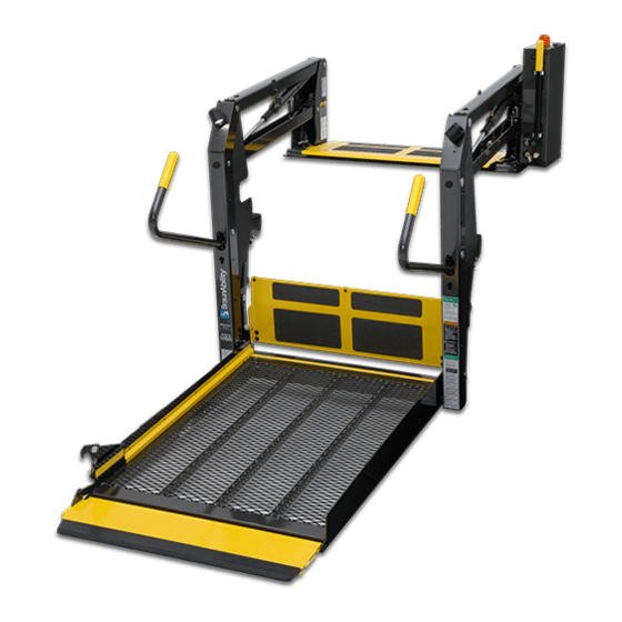
Service Manual for:
Vista
Public Use Wheelchair Lifts
Series
DOT — Public Use Lift
DOT — Public Use Lift
"DOT — Public Use Lift" verifies that this platform lift meets the
"public use lift" requirements of FMVSS No. 403. This lift may be
installed on all vehicles appropriate for the size and weight of the
lift, but must be installed on buses, school buses, and multi-
purpose passenger vehicles other than motor homes with a gross
vehicle weight rating (GVWR) that exceeds 4,536 kg (10,000 lb).
®
®
Winamac, IN 46996 USA
FAX: (574) 946-4670
Patent #6,599,079
Patent #6,599,079
Patent #6,692,217
Patent #6,692,217
Patent #6,739,824
Patent #6,739,824
Patent #6,837,670
Patent #6,837,670
05
05
W A R N I N G
Read manual
before installing
or servicing lift.
Failure to do so
may result in
serious bodily
injury and/or
property damage.
Patents Pending
Patents Pending
Advertisement
Table of Contents

Related Manuals for Braun NVL Vista Series


Summary of Contents for Braun NVL Vista Series
- Page 1 Service Manual for: Vista Public Use Wheelchair Lifts Series DOT — Public Use Lift DOT — Public Use Lift “DOT — Public Use Lift” verifies that this platform lift meets the “public use lift” requirements of FMVSS No. 403. This lift may be installed on all vehicles appropriate for the size and weight of the lift, but must be installed on buses, school buses, and multi- purpose passenger vehicles other than motor homes with a gross...
- Page 2 The warranty cards must be processed to activate the warranty. Two Braun Serial No./Series No. identification tags (shown below) are posted on the lift. One I.D. tag is posted on the opposite pump side vertical arm. A second I.D. tag is located on the opposite pump side tower.
-
Page 3: Table Of Contents
Contents Troubleshooting and Maintenance Lift Terminology............. 2 Switch and Sensor Locations ........3 Certification Checklist Diagnostic Procedures ..4 Platform Fold Pressure Adjustment ......5 Platform Angle Adjustment ........6-7 Platform Stop Blocks ............ 7 Platform Foor Level Adjustment ........8 Bridging Microswitch Adjustment ....... -
Page 4: Lift Terminology
Lift Terminology Hand-Held Pendant Lift-Tite ™ Latches (2) Towers (2) Control Top Parallel Arms (2) Visual Threshold Main Cylinders (2) Warning Audible Unfold Assist Compression Springs (2) Threshold Warning Adjustable Quiet-Ride Stow Blocks (2) Platform Lights Opposite Pump Side Vertical Arm Vertical Arm Covers (4) Threshold Handrails (2) -
Page 5: Switch And Sensor Locations
Switch and Sensor Locations Threshold Strip Switch 31221A (Qty. 2) Right Inboard Left Outboard Stow Microswitch 23184 (Qty. 2) Ground Detect Magnet Ground Detect 31664 Magnetic Sensor 30433A60 Rotary Position Sensor 31194A IB Occupancy Microswitch Assy. 31643A Outer Barrier Raised Magnetic Sensor 30433A60 Bridging... -
Page 6: Certification Checklist Diagnostic Procedures
The following operations and conditions must be functionally verified in order for the lift to be FMVSS 403/404 compliant. If an operation does not function as described or a condition is not met, follow the refer- enced procedures to correct the problem or contact a Braun Corporation Product Support representative at 1-800-THE LIFT ®... -
Page 7: Platform Fold Pressure Adjustment
Platform Fold Pressure Adjustment 1. Position the platform at the floor level loading position. 2. Loosen the hex nut on the adjustment screw (do not remove hex nut). 3. Turn the adjustment screw counter clockwise until the platform does not fold when the Fold button is pressed. -
Page 8: Platform Angle Adjustment
Platform Angle Adjustment Adjusting the platform angle based on the Millennium “NL” Series relationship of the platform at ground level directly affects the angle of the platform Figure C when positioned at floor level. Unfold the lift and visually examine the angle of the platform when positioned at Angle A floor level. -
Page 9: Platform Stop Blocks
Platform Angle Adjustment Adjustment Allen screws are To raise the outboard end Note: Both adjustment screws provided on each side of the lift of platform - turn adjustment must be adjusted equally. platform for adjusting the platform screw clockwise. angle. Adjust platform angle as Apply Loctite ®... -
Page 10: Platform Foor Level Adjustment
Platform Floor Level Adjustment Before setting floor level position: tion if unable to stop platform when powering lift. • Adjust platform angle as detailed on page 6. 2. Turn Lift Power switch Off. • Ensure both stop blocks are 3. Press Floor Position Set but- making full contact with verti- ton (located between pump cal arms (details on page 7). -
Page 11: Bridging Microswitch Adjustment
Bridging Microswitch Adjustment Adjustment Screw Bridging Microswitch Bridging Microswitch: The bridging microswitch is located at the bottom of the right (front) vertical arm. See Photos A and B. An adjust- ment screw is built into the platform stop block. The bridging microswitch will be deactivated if the outboard end of the platform contacts the unloading surface before... -
Page 12: Lcd Lift Codes
LCD Lift Codes To better understand the Braun LCD Trouble shooting display you must first understand the numbers that appear on the screen. There are Flashing Codes, Solid Error Codes, and Solid Normal Operational Codes. Flashing Codes #65-89: About 10 seconds after an operation has stopped there are a set of scrolling flashing numbers that indicate whenever a particular sensor or switch has been activated. - Page 13 LCD Lift Codes Listed below are codes that the lift controller outputs during lift operation. The codes will be displayed on an LCD screen located on the lift control board inside the pump module. See the Manual Operating Instructions in the operator's manual for pump cover removal instructions.
-
Page 14: Lubrication Diagram
Outer Barrier Pivot Points (2) LO Outer Barrier Activation Outboard Platform Rollers and Pins (2) LG Foot Pivot Point (2) LO See the Maintenance/Lubrication Schedule for recommended applications per number of cycles. Specified (recommended) Available Braun Lubricant Type Lubricant Amount Part No. Light Penetrating Oil LPS2, General Purpose 11 oz. -
Page 15: Maintenance And Lubrication Schedule
The maintenance and lubrication procedures specified will vary according to specified by an in this schedule must be performed by a Braun autho- lift use and conditions. authorized service rized service representative at the scheduled intervals Lifts exposed to severe technician. - Page 16 Maintenance and Lubrication Schedule Inspect outer barrier for proper operation Correct or replace damaged parts. Inspect platform fold gear rack and gear weldment Remove foreign objects, replace damaged parts teeth for foreign objects, wear or damage (bent, and resecure as needed deformed or misaligned), positive securement and Cycles proper operation...
- Page 17 Resecure, replace or correct as needed Inspect cotter pins on platform pivot pin (2) ® Use Braun 32840-QT (Exxon Univis HVI 26) Hydraulic Fluid (Pump) - Check level. Note: Fluid hydraulic fluid (do not mix with Dextron III or other should be changed if there is visible contamination.
-
Page 18: Notes
NOTES This page intentionally left blank to provide a place for notes and references. Page 16... -
Page 19: Lift Electrical Schematic
Lift Electrical Schematic BK(24 GA COPPER) BK/WH(24 GA SILVER) NOTE: ALL WIRES ARE 22 GA. LIFT UNLESS OTHERWISE NOTED. SWITCH BOX NOT USED IB JUMPER OR(18) THRESHOLD IB OCCUPANCY SENSOR MICROSWITCH BK(18) DOWN GN(18) FOLD BK/WH(24 GA SILVER) BK(24 GA COPPER) OUTBOARD UNFOLD BARRIER... -
Page 20: Lift Wiring Diagram
Lift Wiring Diagram Platform Lights (Option) 985-A1534NA 6-COND WIRE CODE COLOR BLACK 985-2541NA WHITE GREEN Note: All wires 22 GA. ORANGE JUMPER #1 (CAVITY #2 TO #4) NOT USED ORANGE JUMPER #2 (CAVITY #3 TO #8) NOT USED unless otherwise noted. 13 12 11 10 Lift... -
Page 21: Hydraulic Schematic
Hydraulic Schematic Orifice Orifice Lifting Down Secondary Relief Valve Valve Valve 2500 Folding Relief Valve 1900 Opposite Pump Side Pump Cylinder BACKUP Cylinder PUMP PUMP Description Symbol Description Symbol Fixed Displacement Hydraulic Port Pump 2 Way 2 Position Pump Motor Solenoid Valve Pressure Compensated Backup Pump... -
Page 22: Hydraulics Parts List
* Raw material items ordered and priced per inch (order specified length). (complete) (complete) Coil Coil #31122 #31122 Hydraulic Fluid When adding or changing hydraulic fluid, use Braun 32840-QT (Exxon ® Univis HVI 26) hydraulic fluid (do not mix with Dextron III or Cartridge Cartridge other hydraulic fluids). -
Page 23: Hydraulics Diagram
Hydraulics Diagram Hydraulic Pump Motor Manual Backup Pump Page 21... -
Page 24: Pump Module
(items 26 and 27) if a blue nylon patch is not present on the bolts when retrofitting an M268-0112 pump assembly. Loctite ® is available from The Braun Corporation under part number 11522-1. t Indicates items available for replacement part purposes only. These items are not included with replacement pump modules. -
Page 25: Pump Module Diagram
26 and 27) if a blue nylon patch is not present on the bolts when retrofitting an M268 pump assembly. Loctite ® available from The Braun Corporation under part number 11522-1. Note: Rear pump module shown, front pump module mirror image. -
Page 26: Repair Parts List
Repair Parts List Part Numbers of Items Dedicated per Lift Model Item Qty. Description NVL917IB NVL917FIB Base Weldment 975R5148NW33 975F5148NW33 Cover, Pump, 2-Piece, Back-Bottom 915-0513RNPT 915-0513FNPT Cover, Pump, 2-Piece, Top-Front 915-0519RNPT 915-0519FNPT Assembly, Link, Outer Barrier, Rear 975-0219RNA 975-0220RNA Assembly, Link, Outer Barrier, Front 975-0219FNA 975-0220FNA Bridge Switch Assembly 975-0443RNA 975-0443FNA Block, Platform Stop - Bridging - Rear... -
Page 27: Exploded View
Exploded View 156 157 112 169 182 133 172 122 Page 25... -
Page 28: Notes
NOTES This page intentionally left blank to provide a place for notes and references. Page 26... - Page 29 "Providing Access to the World" ® Over 300 Braun Dealers Worldwide ® "Providing Access to the World" International Corporate Hdqrs: P .O. Box 310 Winamac, IN 46996 USA 1-800-THE LIFT ® (574) 946-6153 FAX: (574) 946-4670...
- Page 30 The Braun Corporation of Winamac, Indiana, warrants that it will repair (or replace at Braun’ s sole option) any defect in material or workmanship in its wheelchair lift for five years*, providing the lift is installed, operated and maintained properly. This warranty is limited to the original purchaser and does not cover defects in the motor vehicle on which it is installed, or defects in the lift caused by a defect in any part of the motor vehicle.
Need help?
Do you have a question about the NVL Vista Series and is the answer not in the manual?
Questions and answers