Table of Contents
Advertisement
"Providing Access to the World"
International Corporate Hdqrs: P.O. Box 310
®
1-800-THE LIFT
(574) 946-6153
34963 Rev. C
December
2009
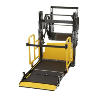
Service Manual for:
Public Use Wheelchair Lifts
Series
DOT — Public Use Lift
DOT — Public Use Lift
"DOT — Public Use Lift" verifies that this platform lift meets the
"public use lift" requirements of FMVSS No. 403. This lift may be
installed on all vehicles appropriate for the size and weight of the
lift, but must be installed on buses, school buses, and multi-
purpose passenger vehicles other than motor homes with a gross
vehicle weight rating (GVWR) that exceeds 4,536 kg (10,000 lb).
®
®
Winamac, IN 46996 USA
FAX: (574) 946-4670
01
01
W A R N I N G
Read manual
before installing
or servicing lift.
Failure to do so
may result in
serious bodily
injury and/or
property damage.
Advertisement
Table of Contents

Related Manuals for Braun NL500 Series


Summary of Contents for Braun NL500 Series
- Page 1 Service Manual for: Public Use Wheelchair Lifts Series DOT — Public Use Lift DOT — Public Use Lift “DOT — Public Use Lift” verifies that this platform lift meets the “public use lift” requirements of FMVSS No. 403. This lift may be installed on all vehicles appropriate for the size and weight of the lift, but must be installed on buses, school buses, and multi- purpose passenger vehicles other than motor homes with a gross...
- Page 2 The warranty cards must be processed to activate the warranty. Two Braun Serial No./Series No. identification tags (shown below) are posted on the lift. One I.D. tag is posted on the right side vertical channel. A second I.D. tag is located on the lift mounting base.
-
Page 3: Table Of Contents
Outer Vertical Channel - Rear ....... 27 Handrail Assembly ..........28 Platform Assembly ..........29 Platform Sub-Assembly - Inner ......30 Platform Sub-Assembly - Inner Side Plate ..31 Platform Sub-Assembly - Outer ......32 Warranty Braun ® Limited Warranty ........33-35 Page 1... -
Page 4: Lift Terminology
Lift Terminology Raise / Lower Stow / Deploy Hydraulic Hydraulic Cylinder Cylinder Inner (not visible) Mounting Intermediate Vertical Base Vertical Channel (2) Raise / Lower Channel Hydraulic (S-Beam)-2 Cylinder (not visible) Outer Vertical Pump Channel (2) Module Inner Right Roll Stop Handrail Handrail Belt... -
Page 5: Switch And Sensor Locations
Switch and Sensor Locations Inner Roll Stop Up Activation Block Inner Roll Stop Occupied Switch 15754 Inner Roll Stop Deployed - Floor Level Cam (Outer) 500-0015 Inner Roll Stop Deployed - Floor Level Cam (Inner) 500-0014 Platform Unfold Limit Switch 30205 Full In Limit Switch... -
Page 6: Certification Checklist Diagnostic Procedures
Platform Lift Installations in Motor Vehicles (49 CFR the referenced procedures to correct the problem 571.404). or contact a Braun Corporation Product Support representative. • Vehicle movement is prevented unless the lift door is closed, ensuring the lift is stowed. -
Page 7: Switch Adjustments
Switch Adjustments Adjustment Procedures Full In: When the Full In Switch is deactivated (de- point when the Inner Roll Stop is locked in the upright pressed), inward travel of the lift during Stow function position. This deactivation stops the downward travel is stopped. -
Page 8: Lcd Diagnostic Codes
CYCLE Repeat the harness diagnostic procedure. If an incorrect value is still present after check- ing the harness and connections, contact The Braun Corporation Product Support Lift_Out Floor_SW ® Department. LCD MODULE... - Page 9 NOTES This page intentionally left blank. Page 7...
-
Page 10: Lubrication Diagram
Bracket Slot (2) Outer Barrier (both sides) Latch Split Foot Pivot See the Maintenance/Lubrication Schedule for recommended applications per number of cycles. Specified (recommended) Available Braun Lubricant Type Lubricant Amount Part No. Light Penetrating Oil LPS2, General Purpose 16 oz. -
Page 11: Maintenance And Lubrication Schedule
NL500 Series lifts are equipped with hardened pins repeated at 750 cycle intervals following the scheduled and self-lubricating bushings to decrease wear, 4500 cycle maintenance procedures. These intervals... - Page 12 Resecure or replace damaged fasteners. See Ex- tive securement. ploded View section for fasteners that require #242 General Purpose Blue Loctite (Braun #18822). Remove pump module cover and inspect: Resecure, replace or correct as needed. • Hydraulic hoses, fittings and connections for wear or leaks on pump, valve block and hand pump.
- Page 13 • Spring tensions pulley bracket (1) • Vertical channel chain pins (8) • Platform pivot pins (2) Hydraulic Fluid (Pump) - Check level. Note: Fluid Use Braun 32840-QT (Exxon ® Univis HVI 26) should be changed if there is visible contamination.
- Page 14 NOTES This page intentionally left blank. Page 12...
-
Page 15: Lift Electrical Schematic
Lift Electrical Schematic DESCRIPTION SYMBOL BATTERY CHASSIS GROUND RD(20) CIRCUIT BREAKER / FUSE RD(20) JUNCTION MOTOR SOLENOID LIFT INPUTS SOLENOID BK(22) RD(18) RD(20) SWITCH BK(18) STOW LEVEL FULL OUT MICROSWITCH MICROSWITCH MICROSWITCH BK(26) GN(22) GN(26) DIODE YL(26) RD(22) BU(26) RD(20) WH(26) RD(26) LIFT CONTROL MODULE... -
Page 16: Lift Wiring Diagram
Lift Wiring Diagram NOTES: Ground 6-COND WIRE CODE 6-COND WIRE CODE 1. Junctions occur only at Stud COLOR COLOR marked intersections. GREEN(16) SOLENOID A LIFT INPUTS 34298A BU(18) BROWN(16) SOLENOID B YELLOW(16) SOLENOID C SOLENOID D RED(16) OR(20) BK(18) BK(18) BLACK(16) NOT USED NOT USED... - Page 17 NOTES This page intentionally left blank. Page 15...
-
Page 18: Hydraulic Parts List
Kit, Valve Block - Check Valve (Qty. 1) / Relief Valves (Qty. 2) - Not Shown 34903K Hydraulic Fluid When adding or changing hydraulic fluid, use Braun 32840-QT (Exxon ® Univis HVI 26) hydraulic fluid (do not mix with Dex- tron III or other hydraulic fluids). -
Page 19: Hydraulic Diagram
Hydraulic Diagram Arrow must face valve block Page 17... - Page 20 NOTES This page intentionally left blank. Page 18...
-
Page 21: Hydraulic Schematic
Hydraulic Schematic .5 GPM Relief Valve 1500 Relief Valve 1500 Rear Front In/Out In/Out Cylinder Cylinder “B” Valve “C” “A” “D” Valve Valve Valve Valve Block Main Relief Valve 2000 PUMP 1900 Rear Front Up/Down Up/Down Cylinder Cylinder BACKUP Reservoir PUMP Description Symbol... -
Page 22: Mounting Base
Exploded Views and Parts Lists Mounting Base DWG. NOTES 1) APPLY "GREASE-MOBILTEMP SHC 32" B.C.#28598 WHEN REPLACING ALL BEARINGS . 2) APPLY ALCOHOL TO BRACKET B.C. #500-0018 PRIOR TO APPLYING BUMPERS B.C. #82064 NOTE: 2 NOTE: 1 NOTE: 1 34894-F24 SOLENOID-TROMBETTA-24 V./VENDOR #17808 51267 GROM-ID .88"/GR .06"/GD 1.25"/.3"... -
Page 23: Upper / Lower Control Arms
Exploded Views and Parts Lists Upper / Lower Control Arms - Front DWG. NOTES 1) APPLY " GREASE-MOBIL TEMP SCH 32 " B.C. #28598 TO BEARINGS ON B.C. #500-0055FA. NOTE: 2 2) APPLY " LOCTITE-BLUE/#242 GEN PURPOSE " B.C. #18822 TO B.C. -
Page 24: Inner Vertical Channel - Front
Exploded Views and Parts Lists Inner Vertical Channel - Front DWG. NOTES 1) PARTS 500-0128 AND 500-0175A TO BE LOCATED TOWARD INSIDE OF CHANNEL 10X. 2) PARTS 500-0110 AND 500-0101A TO BE LOCATED TOWARD OUTSIDE OF CHANNEL 8X. 3) APPLY " GREASE-MOBIL TEMP SCH 32 " B.C. #28598 TO INSIDE ROLLERS PRIOR TO ASSEMBLY 18X. -
Page 25: Inner Vertical Channel - Rear
Exploded Views and Parts Lists Inner Vertical Channel - Rear DWG. NOTES 1) PARTS 500-0128 AND 500-0175A TO BE LOCATED TOWARD INSIDE OF CHANNEL 10X. 2) PARTS 500-0110 AND 500-0101A TO BE LOCATED TOWARD OUTSIDE OF CHANNEL 8X. 3) APPLY " GREASE-MOBIL TEMP SCH 32 " B.C. #28598 TO INSIDE ROLLERS PRIOR TO ASSEMBLY 18X. -
Page 26: Intermediate Vertical Channel (S-Beam) - Front
Exploded Views and Parts Lists Intermediate Vertical Channel (S-Beam) - Front DWG. NOTES 1) APPLY " GREASE-MOBIL TEMP SHC 32 " B.C. #28598 TO INSIDE ROLLER PRIOR TO ASSEMBLY. NOTE: 1 500-0736 GUARD-CHAIN ROLLER 21708R021 CHAIN-LEAF-4x4-.5 PITCH x 21" 21759 PIN-COTTERED-4x4 LEAF CHAIN 23173 PIN-COTTER 1/32 x 1/2 (4x4) -
Page 27: Intermediate Vertical Channel (S-Beam) - Rear
Exploded Views and Parts Lists Intermediate Vertical Channel (S-Beam) - Rear DWG. NOTES 1) APPLY " GREASE-MOBIL TEMP SHC 32 " B.C. #28598 TO INSIDE ROLLER PRIOR TO ASSEMBLY. NOTE: 1 500-0736 GUARD-CHAIN ROLLER CHAIN-LEAF-4x4-.5 PITCH x 21" 21708R021 21759 PIN-COTTERED-4x4 LEAF CHAIN 23173 PIN-COTTER 1/32 x 1/2 (4x4) -
Page 28: Outer Vertical Channel - Front
Exploded Views and Parts Lists Outer Vertical Channel - Front DWG. NOTES NOTE: 1 1) PARTS 500-0128 AND 500-0175A TO BE 3) APPLY "GREASE-MOBIL TEMP SCH 32" B.C. NOTE: 3 #28598 TO INSIDE ROLLERS PRIOR TO LOCATED TOWARD INSIDE OF CHANNEL 8X. -
Page 29: Outer Vertical Channel - Rear
Exploded Views and Parts Lists Outer Vertical Channel - Rear DWG. NOTES NOTE: 1 1) PARTS 500-0128 AND 500-0175A TO BE LOCATED TOWARD INSIDE OF CHANNEL 8X. NOTE: 3 2) PARTS 500-0110 AND 500-0101A TO BE LOCATED TOWARD OUTSIDE OF CHANNEL 10X. 3) APPLY "... -
Page 30: Handrail Assembly
Exploded Views and Parts Lists Handrail Assembly - Front DWG. NOTES 1) INSERT BOLT THROUGH CAM AND THREAD INTO SHAFT AFTER SHAFT HAS BEEN INSTALLED INTO HANDRAIL. NOTE: 1 NOTE: 1 10059BKWP NUT-3/8-16 HEX/AUTO-BK-WITH PATCH 28977 BOLT-3/8-16 X 1 3/4 " FLBHSCS-GD8 19471T-M BELT-RETRACTOR ONLY/NON-LOCKING/AMSAFE NOTE: 1... -
Page 31: Platform Assembly
Exploded Views and Parts Lists Platform Assembly DWG. NOTES 1) INSTALL PARTS B.C. #34357 AND B.C. 325371 AFTER OUTER PLATFORM IS INSTALLED INTO PLACE. 2) LOCATE SPRING HOOK INTO SPRING ATTACHMENT BRACKET ON THE BOTTOM SIDE OF THE PLATFORM INNER DECK. 3) USE (3) SCREWS FROM INNER ASSEMBLY AND RIVETS TO INSTALL GUARD INTO PLACE. -
Page 32: Platform Sub-Assembly - Inner
Exploded Views and Parts Lists Platform Sub-Assembly - Inner DWG. NOTES 1) USE " LOCTITE-BLUE/GEN PURPOSE " B.C.#18822 ON ALL THREADS DURING ASSEMBLY. 2) APPLY "GREASE-MOBILTEMP SHC 32" B.C.#28598 TO PULLEY INNER HOLE AND INSERT INTO SLOT BEFORE BOLTING INTO PLACE. 3) PLACE HINGE B.C. -
Page 33: Platform Sub-Assembly - Inner Side Plate
Exploded Views and Parts Lists Platform Sub-Assembly - Inner Side Plate (Front) DWG. NOTES 1) APPLY "LOCTITE-BLUE /#242 GEN PURPOSE" B.C.#18822 TO ALL THREADS DURING ASSEMBLY. 500-0156 HANDRAIL SUPPORT BRACKET 81027-000 SCREW-1/4-20 X 1-1/4 FHSC 25527 SCREW-5/16-18 X 3/4 " FHS/AUTO-BK 40-2836-0 SCREW-1/4 "-20 X .875 BHSC 18860... -
Page 34: Platform Sub-Assembly - Outer
Exploded Views and Parts Lists Platform Sub-Assembly - Outer DWG. NOTES 1) USE "LOCTITE-BLUE/#242 GEN PURPOSE" B.C.# 18822 ON ALL THREADS DURING ASSEMBLY. 2) ROUTE HARNESS THRU STRAIN RELIEF (ITEM #40). 3) ROUTE HARNESS THRU CLAMP (ITEM #30). NOTE: 3 NOTE: 2 24028 BEARING-PLASTIC-FLANGE-3/8ID X 1/4"... -
Page 35: Braun Limited Warranty
first retail purchaser by an independent, authorized dealer of Braun, or, if the dealer places the product into any type of service prior to retail sale, on the date the dealer first places the product in such service. - Page 36 You must inspect the product for this type of damage when you take delivery. If you find any such defect or damage you must notify the selling dealer, or Braun, at the time of delivery to have these items covered by this limited warranty and to have work performed on the items at no cost to you as provided by this limited warranty.
- Page 37 Braun will do and does not guarantee anything about the product for any time period. Nothing in this warranty, or any action of Braun, or any agent of Braun, shall be interpreted as an extension of any warranty period or the filing limitation period in this paragraph. Some states do not allow a reduction in the statute of limitations, so this reduction may not apply to you.
- Page 38 NOTES This page intentionally left blank. Page 36...
- Page 39 "Providing Access to the World" ® Over 300 Braun Dealers Worldwide ® "Providing Access to the World" International Corporate Hdqrs: P .O. Box 310 Winamac, IN 46996 USA 1-800-THE LIFT ® (574) 946-6153 FAX: (574) 946-4670...
- Page 40 All illustrations, descriptions and specifications in this manual are based on the latest product information available at the time of publication. The Braun Corporation reserves the right to make changes at any time without notice. at the time of publication. The Braun Corporation reserves the right to make changes at any time without notice.
Need help?
Do you have a question about the NL500 Series and is the answer not in the manual?
Questions and answers