Advertisement
Quick Links
33220
"Providing Access to the World"
International Corporate Hdqrs: P.O. Box 310
1-800-THE LIFT
®
(574) 946-6153
37717 Rev. A
April 2012
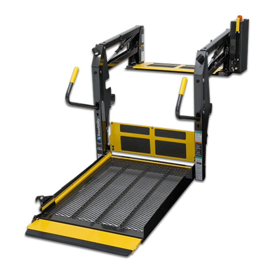
Service Manual for:
NCL954
Century
Series
Public Use Wheelchair Lifts
Series
DOT — Public Use Lift
DOT — Public Use Lift
"DOT — Public Use Lift" verifies that this platform lift meets the
"public use lift" requirements of FMVSS No. 403. This lift may be
installed on all vehicles appropriate for the size and weight of the
lift, but must be installed on buses, school buses, and multi-
purpose passenger vehicles other than motor homes with a gross
vehicle weight rating (GVWR) that exceeds 4,536 kg (10,000 lb).
®
®
Winamac, IN 46996 USA
FAX: (574) 946-4670
2
2
FA
FA
W ARNING
Read manual
before installing
or servicing lift.
Failure to do so
may result in
serious bodily
injury and/or
property damage.
Advertisement

Related Manuals for Braun NCL954


Summary of Contents for Braun NCL954
- Page 1 Service Manual for: NCL954 Century Series Public Use Wheelchair Lifts Series DOT — Public Use Lift DOT — Public Use Lift “DOT — Public Use Lift” verifies that this platform lift meets the “public use lift” requirements of FMVSS No. 403. This lift may be...
- Page 2 The warranty cards must be processed to activate the warranty. Two Braun Serial No./Series No. identification tags (shown below) are posted on the lift. One I.D. tag is posted on the opposite pump side vertical arm. A second I.D. tag is located on the opposite pump side tower.
-
Page 3: Table Of Contents
Contents Troubleshooting and Maintenance Lift Terminology..............2 Switch and Sensor Locations ......... 3 ....4 ......... 5 .......... 6-7 ............7 ........8 ............10 Lift Electrical Schematic ..........15 ............16 Hydraulics ............. 17 ............. 18 ............19 Repair Parts Pump Module .......... -
Page 4: Lift Terminology
Lift Terminology Lift Terminology Towers (2) (Rear) Main Cylinders (2) Threshold Warning Threshold Hand-Held Warning Pendant Control Lift-Tite ™ Latches (2) Platform Lights (2) Threshold Handrails (2) Warning Plate Base Plate Inner Roll Stop Bottom Parallel Saddle (2) Platform Platform Side Plates (2) Right Left Page 2... -
Page 5: Switch And Sensor Locations
Switch and Sensor Locations *Threshold Alarm & Partial Fold Microswitch Assy. 975-4121A *Threshold Alarm Threshold Strip Switch *Partial Fold Microswitch 33337A (2 strips per) Microswitch *Up & Unfold Right Inboard Microswitch Assy. 975-4121A *Up Microswitch Outboard Left *Unfold Microswitch Stow Interlock Microswitch IB Occupied IB Occupied &... - Page 6 Certification Checklist Diagnostic Procedures 3. Reinstall threshold warning plate. Page 4...
- Page 7 Platform Fold Pressure Adjustment pressed. platform. Do not adjust this valve. (located beside solenoid valves) Platform Fold screw and tighten hex Page 5...
- Page 8 Platform Angle Adjustment Figure A Barrier Heel Platform heel The angle of the platform at the angle of the platform when platform. Figure B Floor Wedges (option) Adjustment Procedure: of the platform (see photo at right When and details on following page). Vertical Stop arms (see photo at right and...
- Page 9 Platform Angle Adjustment ® to lower end of platform to raise end of platform Platform Stop Blocks Right Wrong Gap not permitted. Stop Block Guideline All Lift Models Vertical Stop Vertical Stop Page 7...
- Page 10 Tower Microswitch Adjustment TOWER TOWER TOWER TOWER 32943 32942 Figure B TOWER TOWER TOWER TOWER 32943 32942 lift is a mirrored image. as needed only. Tower 1 (Unfold) Switch Adjustment Tower 3 (Alarm) Switch Adjustment Floor Position from Stow dant control. Tower 4 (Fold) Switch Adjustment Partial Fold Switch of the saddle and the lower parallel...
- Page 11 NOTES Page 9...
- Page 12 Maintenance and Lubrication Lubrication Diagram Lift-Tite ™ (2 springs - 4 Points) LO Lift-Tite ™ Latches Saddle Bearing (2) Bearings (4) Roller Pin Bearings (4) Inner Roll Stop Bearings (8) and Slots (2) Inner Roll Stop Cam Followers (4) Bearings (8) Lift-Tite ™...
- Page 13 Maintenance and Lubrication Schedule W ARNING Maintenance and lubrication procedures must be performed as 4500 cycle maintenance authorized service technician. Failure to do so may result in serious bodily injury and/or property damage. life of the lift. Cycle Counter: NCL-2 Series lift models are to the components.
- Page 14 Maintenance and Lubrication Schedule spring(s) Cycles Correct as needed. condition Correct as needed. Inspect lift for rattles Perform all procedures listed in previous section also Inner fold arm cam followers (4) 1500 Cycles Inspect Lift-Tite ™ Inspect inner roll stop for: Replace damaged parts.
- Page 15 Maintenance and Lubrication Schedule Inspect external snap rings: ™ latch rollers (2) ™ latch gas (dampening) springs (4) 1500 Cycles Perform all procedures listed in previous section also ® Replace if needed. 4500 Cycles Tighten or replace if needed. Replace if needed. Inspect gas springs (cylinders - 6) for wear or dam- Page 13...
- Page 16 Maintenance and Lubrication Schedule 4500 Cycles Consecutive 750 Cycle Intervals Page 14...
-
Page 17: Lift Electrical Schematic
Lift Electrical Schematic RD(18) IB RAISED PLATFORM LIGHTS DESCRIPTION SYMBOL (OPTION) SWITCH BK(18) RD(18) BK(18) GN(20) CAPACITOR BK(22) BK(20) BK(18) BK(18) RD(18) RD(22) VT(20) MICROSWITCH LIFT BK(18) RD(18) GN(20) LIGHT BK(18) BK(18) RD(18) SWITCH BOX RELAY OUTER BARRIER DIODE OCCUPIED / RAISED RD(18) OR(20) BK(18) - Page 18 Lift Wiring Diagram Light Relay RD(18) Platform Lights (Option) RD(18) Counter 4-COND WIRE CODE 4-COND WIRE CODE COLOR COLOR BLACK(18) BLACK(18) BLUE(18) RED(18) WHITE(18) WHITE(18) GN(18) NOT USED NOT USED GN(20) GN(20) GN(18) SILVER(22) WH(18) SILVER(22) 6-COND WIRE CODE 6-COND WIRE CODE COLOR COLOR 1 2 3...
- Page 19 Hydraulic Schematic Orifice Orifice Lifting Down Secondary Relief Valve Valve Valve 2500 Folding Relief Valve 1900 Opposite Pump Side Pump Cylinder BACKUP PUMP Cylinder PUMP Description Symbol Description Symbol Fixed Displacement Hydraulic Port Pump 2 Way 2 Position Pump Motor Solenoid Valve Pressure Compensated Backup Pump...
- Page 20 Hydraulics Parts List Item Qty. Description Part # Pump Assembly (M-268-0114) 120G / 12V / Dual Relief 32858-12V Solenoid, 4-Post Trombetta - Angle 35310 Motor, Pump - 12 Volt - Low RPM 29690 Valve Assembly, “Dual Relief" (complete) 31120K Cartridge (only), “Dual Relief" Valve - (shown below) 31121 Coil (only) - (shown below) 31122...
-
Page 21: Hydraulics
Hydraulics Diagram Hydraulic Repair For repair of a hydraulic hose or cylinder, read this. Service Hydraulic Bulletin 27049 Pump Motor Manual Backup Pump Page 19... -
Page 22: Pump Module
Pump Module Parts List Item Qty. Description NCL954FIB-2 NCL954IB-2 Pump Module (complete), 12 Volt, Rear 954-5516FNA 954-5516RNA Pump Assembly (M268-0114) 12V-120G - Dual Relief (Includes Items 1, 2 & 20) 32858-12V 32858-12V Solenoid, Up - 4-Post Trombetta - Angle 35310 35310 Housing, Pump 947-2513FN... - Page 23 Pump Module Diagram Pump Mounting Bolts Apply Loctite ® Threadlocker Red 271™ or equivalant to the three pump mount- ing bolts (items 25 and 26) if a blue nylon patch is not present on the bolts sembly. Note: Rear pump module shown, front pump module mirror image.
- Page 24 Exploded Views and Parts Lists NCL954IB-2 Base Plate Assembly DWG. NOTES 1) LOOP TAPESWITCH WIRE BACK AND SECURE WITH WIRE TIE 4X. 2) TRIM AND TUCK WIRE TIE CLASP INTO HOLE 4X. 3) APPLY LOCTITE ® THREADLOCKER RED 271™ OR EQUIVALANT TO ALL #25527 SCREWS. NOTE: "A"...
- Page 25 Exploded Views and Parts Lists NCL954FIB-2 Base Plate Assembly DWG. NOTES 1) LOOP TAPESWITCH WIRE BACK AND SECURE WITH WIRE TIE 4X. 2) TRIM AND TUCK WIRE TIE CLASP INTO HOLE 4X. 3) APPLY LOCTITE ® THREADLOCKER RED 271™ OR EQUIVALANT TO ALL #25527 SCREWS. NOTE: "A"...
- Page 26 Exploded Views and Parts Lists Top Parallel Arm Assembly - Front ITEM QTY. PART NO. DESCRIPTION 10062 WASHER-1/4" FLAT/AUTO-BK 30996BK NUT-5/16-18 ACORN 10068 WASHER-5/16" LOCK/AUTO-BK 15858BK BOLT-CARR 5/16-18 X 3/4/AUTO-BK 16368 WASHER-5/16" EXTERNAL TOOTH 24440 BOLT-5/16-18 X 3/4-BHSC/AUTO-BK 28593A ASSY-BLOCK-GUIDE-PLATFORM-STOW 955-2392CLXT BKT.-QUIET-RIDE MTG.-955 14993...
- Page 27 Exploded Views and Parts Lists Bottom Parallel Arm Assembly - Rear PART NO. DESCRIPTION ITEM QTY. 18349 NUT-#10-32 W/LOCKWASHER/AUTO-BK 32514NA ASSY-IB OCCUPIED 34398 WASHER-0.906"ID X 1.25"OD X .075"TH/ZINC 24011 BEARING-FLANGE-3/4" X 3/8"-12FDU06 954-0412NA ASSY-ARM-PARALLEL/BOTTOM/PUMP (Incl. Items 1-3) Bottom Parallel Arm Assembly - Front ITEM QTY.
- Page 28 Exploded Views and Parts Lists Hydraulic Cylinder Assembly - Main RETRACTED 32.217 STROKE 16.499 EXTENDED 48.716 30° ±10° PART NO. DESCRIPTION ITEM QTY. 15150 ELBOW-1/4 NPT 90° 1/4 BARB 26667 ELBOW-7/16-20 M/O-RNG/37*/.035 ORFICE C1516.5-0409 CYLINDER-16.499"/32.217 RETRACTED Page 26...
- Page 29 Exploded Views and Parts Lists Vertical Arm Assembly - Front DWG. NOTES 1) INSERT SOCKET OF LIGHT ASSY THRU TOP KEY WHILE INSTALLING LIGHT. TIGHTEN SCREWS. NOTE: 1 2) APPLY LOCTITE ® THREADLOCKER BLUE 242 ® OR EQUIVALENT 3) APPLY LOCTITE ®...
- Page 30 Exploded Views and Parts Lists Arm Cover Assembly - Front SMOOTH SIDE SMOOTH SIDE ITEM QTY. PART NO. DESCRIPTION 915-0704NA COVER-PLASTIC-PARALLEL ARM-OUTSIDE-FRONT 945-0701NA COVER-PLASTIC-PARALLEL ARM-INSIDE-FRONT Arm Cover Assembly - Rear SMOOTH SIDE SMOOTH SIDE ITEM QTY. PART NO. DESCRIPTION 945-0703NA COVER-PLASTIC-PARALLEL ARM-INSIDE-REAR 915-0702NA COVER-PLASTIC-PARALLEL ARM-OUTSIDE-REAR...
- Page 31 Exploded Views and Parts Lists Front Handrail Assembly ITEM QTY. PART NO. DESCRIPTION 11513 RIV-POP-SD64BS-3/16"-.13/.25/AUTO-BK 10069 WASHER-3/8" LOCK 29186A GAS SPRING ASSY-14.468 EXT/8.956 COMP 30227 SPACER-UHMW 0.75 OD X 0.39 ID X 0.25 13617 NUT-3/8-16 UNC HEX LOCK/AUTO-BK 954-0640FNA ASSY-FOLD ARM-48 FTG-FRONT 31677 SLIDE-UHMW-PLATFORM SLIDE-2X6.9"...
- Page 32 Exploded Views and Parts Lists NCL954IB-2 & NCL954FIB-2 Platform Assembly DWG. NOTES 1) USE LOCTITE ® THREADLOCKER RED 271™ OR EQUIVALENT ON SCREWS (B.C. #24537 AND B.C. 15733 2) USE LOCTITE ® THREADLOCKER GREEN 290™ OR EQUIVALENT ON CLEVIS PINS (B.C. #24932BK) 3) APPLY BOUNDARY DECAL (ITEM 33) 48 1/8"...
-
Page 33: Limited Warranty
10,000 cycles and the cost of labor to repair or replace those parts for one (1) year or 3,000 cycles. If The Braun Corporation receives the warranty registration card within 20 days after the lift is put into service, the warranty labor coverage will increase from one (1) year or 3,000 cycles to three (3) years or 10,000 cycles. - Page 34 (30) days for repairs to be com- pleted, you must, to the extent permitted by law, notify Braun directly, in writing, at the above address, of the unsuccessful repair(s) of the alleged defect(s) so that Braun can become directly involved in providing service pursuant to the terms of this limited warranty.
- Page 35 Braun will do and does not guarantee anything about the product for any time period. Nothing in this warranty, or any action of Braun, or any agent of Braun, shall be interpreted as an extension in the statute of limitations, so this reduction may not apply to you.
- Page 36 NOTES This page intentionally left blank. Page 34...
- Page 37 "Providing Access to the World" ® Over 300 Braun Dealers Worldwide ® "Providing Access to the World" International Corporate Hdqrs: P .O. Box 310 Winamac, IN 46996 USA 1-800-THE LIFT ® (574) 946-6153 FAX: (574) 946-4670...
- Page 38 All illustrations, descriptions and specifications in this manual are based on the latest product information available at the time of publication. The Braun Corporation reserves the right to make changes at any time without notice. at the time of publication. The Braun Corporation reserves the right to make changes at any time without notice.
Need help?
Do you have a question about the NCL954 and is the answer not in the manual?
Questions and answers