Advertisement
Quick Links
These instructions indicate how to build the same Arduino-type smart robot vehicle. It states how to
install step by step robot chassis, Arduino compatible motherboard, Shield module, geared motors, battery
holder and the other accessories as well as their wiring system.
With this project, you will learn how to program the Arduino system and its learning platform.
It should be noted that to assemble this kit, only a screwdriver is needed, NOT INCLUDED
included. All electrical and electronic parts can be connected or screwed into a terminal block or Clema.
The system of infrared light sensors which are installed on the front part basis, detects the black line
that you done on the floor with an adhesive tape forming a way. The intelligent robot will perfectly follow the
drawn path as complicated or long as it is.
Line tracker Robot (with infrared system)
Arduino System
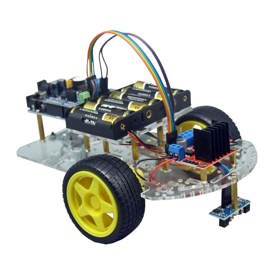
Views of the built robot
www.cebekit.es
sat@fadisel.com
C-9875
Advertisement

Related Manuals for Cebekit C-9875


Summary of Contents for Cebekit C-9875
- Page 1 C-9875 Line tracker Robot (with infrared system) Arduino System These instructions indicate how to build the same Arduino-type smart robot vehicle. It states how to install step by step robot chassis, Arduino compatible motherboard, Shield module, geared motors, battery holder and the other accessories as well as their wiring system.
- Page 2 C-9875 www.cebekit.es sat@fadisel.com...
-
Page 3: Packing List
C-9875 PACKING LIST List of components Nº Name Description Qty. Nº Name Description Qty. Control motherboard Type Arduino UNO R3 14 Metal spacer M3 x 10 mm Shield Module Interface for the 15 Cable with connectors Length 20 cm 2 poles... -
Page 4: Installation And Assembly
C-9875 INSTALLATION AND ASSEMBLY Step 1: Chassis for the Arduino robot We will use: (1) Acrylic chassis for intelligent robot (2) Acrylic support for motors (3) Gearbox motor with double axis and cables (4) Wheel Ø65mm with rubber tire (5) M3 × 30 mm screws (6) M3 Nuts (7) M3 ×... - Page 5 C-9875 Gearbox with double axis Figure 1 – 3: (A) Location of the grooves where the acrylic supports of the motors must be inserted (B) Motors Acrylic supports (C) Screws and nuts to fix motors to the supports Outgoing element Figure 1 –...
- Page 6 C-9875 Mounting support and fixing of the motors Figure 1- 6: Important The chassis is not symmetrical. If you assemble it upside down you will not be able to install the control circuit board. This image shows the chassis seen from the side of the motors (lower side).
- Page 7 C-9875 Figure 1- 9: Then place one screw and one nut in the upper hole and another in the lower hole. See added picture The lower nut will not turn once the screw is tightened because it is in abutment with the chassis.
- Page 8 C-9875 Robotic Free wheel Fix the wheel with M3×8 screws and M3 nuts, as it is indicated on following figures Figure 1- 11:Holes where must be fixed the wheel. Figure 1- 12:Wheel in its correct position before its fixing. www.cebekit.es...
- Page 9 C-9875 Figure 1- 13:Nuts are placed on the lower parts of the chassis. Figure 1- 14:Insert by pressure the two large wheels on the outer axis of each gearbox motor Bottom view of the chassis www.cebekit.es sat@fadisel.com...
- Page 10 C-9875 CAUTION: Disconnect the modules. We will use: (1)Control board Arduino type (2)Shield Module The Arduino main board is supplied already assembled with the Shield module in order to not damage connectors. It will be necessary to unplug them according to the following instructions:...
- Page 11 C-9875 Step 2. Main control electronic Circuit, Arduino Uno Type We will use: (1)Smart Robotic chassis with all wheels (2)Module Arduino Uno Type (3)M3×8 mm Screw (4)M3x25 mm Metal spacer (5)Necessary tools: Screwdriver Figure 2- 1:Necessary pieces to install the main control circuit www.cebekit.es...
- Page 12 C-9875 Figure 2- 2:Fix the four cylindrical spacer as it is indicated on the figure Figure 2- 3:Main control circuit indicating the four fixing points www.cebekit.es sat@fadisel.com...
- Page 13 C-9875 Figure 2- 4:Main control circuit fixed with screws www.cebekit.es sat@fadisel.com...
- Page 14 C-9875 Step 3: Shield Module (interface) We will use: (1)Robot (2)Shield Module Figure 3- 1:Installation of the Shield module. Carefully, connect once again the module on the main control board Attention with the Shield module and the Main control circuit 1.- Before connecting, carefully check the position of the Shield module...
- Page 15 C-9875 Step 4:Batteries-holder We will use: (1)Robot (2)Batteries-holder (3)M3×25 Metal spacer (4)M3 × 10 mm screw (5)Support acrylic board of the batteries holder (6)M3 Nut (7)Necessary Tools : Screwdriver Figure 4- 1:Necessary pieces www.cebekit.es sat@fadisel.com...
- Page 16 C-9875 Figure 4- 2: Spacers location Acrylic board fixing Figure 4- 3: www.cebekit.es sat@fadisel.com...
- Page 17 C-9875 Figure 4- 4: Preparation to fix the batteries-holder. Figure 4- 5:Batteries-holder once screwed7fixed www.cebekit.es sat@fadisel.com...
- Page 18 C-9875 Step 5: Control Circuit of motors We will use: (1)Robot (2)Control circuit of motors (3)M3×10 mm Metal spacer (4)M3 × 10 mm Screw (5)M3 × 8 mm Screw (6)Necessary tools : Screwdriver Figure 5- 1:Pieces that we will use to fix the control circuit of motors www.cebekit.es...
- Page 19 C-9875 Figure 5- 2:Spacers positions Figure 5- 3:Control Circuit once fixed www.cebekit.es sat@fadisel.com...
- Page 20 C-9875 Step 6 - Black lines follower We will use: (1)Basic Robot previously assembled (2)Black Line follower Module (3)M3 × 25 mm Metal spacer (4)M3 × 10 mm Screw (5)Necessary tolls : Screwdriver Figure 6 - 1:Necessary pieces www.cebekit.es sat@fadisel.com...
- Page 21 C-9875 Figure 6- 2:Follower module once fixed to the spacer Figure 6- 3:Line follower Module once fixed to the robot (superior & inferior views). Attention to the position : Do not install upside down. www.cebekit.es sat@fadisel.com...
- Page 22 C-9875 Step 7: Smart robot wiring 1. Connection of the Batteries-holder Figure 7- 1:Batteries-holder wiring Batteries-holder Circuit Arduino UNO type with the Shield module assembled RED Cable Terminal + (positive) of the terminal block feed BLACK Cable Terminal + (negative) of the terminal block feed www.cebekit.es...
- Page 23 C-9875 2. Motors connexion Figure 7- 2: Insert the motor cables through the hole in the center of the acrylic support and up to motor control module. LEFT RIGHT Motor Motor Figure 7- 3: Connect the left motor cables to the left side of the motor control module (A1 and A2 terminals) and those of the right motor to the right side (B1 and B2 terminals).
- Page 24 C-9875 Step 8: Connection between motors control module and shield module Figure 8 – 1 : Locations of contacts on the shield module Figure 8 - 2:Connector once connected on the Shield module www.cebekit.es sat@fadisel.com...
- Page 25 C-9875 Figure 8 – 3 : View of the other extremity of the connector connected to the motor control module. Pay attention to the polarity. Motors control module Shield Module www.cebekit.es sat@fadisel.com...
- Page 26 C-9875 Connection of the power supply to the motors control module Figure 8 – 4 : To supply the motors control module it is necessary to use a special cable. At a first extremity there are two connectors with two male lug pins which are connected to the terminal block of the motors control module.
- Page 27 C-9875 Figure 8 – 8: View of the location of the terminals on the Shield module They are indicated on the module as: 9V (positive) and GND (negative) Figure 8 – 9 : Cable connection on the Shield module. Pay attention to the polarity.
- Page 28 C-9875 Figure 8 – 10 : View of the robot, completely finished, where it is possible to appreciate the power supply connection of the motors control module. The colors of the cables may vary depending on the photographed model. Motors control Module...
- Page 29 C-9875 Step 9: Infrared sensor connection We will use the 4-poles cable which has at one extremity a male connector and at the other extremity a female connector Figure 9 – 1: It is necessary to pass the male connector through the rectangular hole of the acrylic chassis.
- Page 30 C-9875 Figure 9 – 3 : View of the connector and sensor Figure 9 – 4 : View of the sensor, correctly aligned, the screw tight. It is possible to appreciate the polarity of the connection. www.cebekit.es sat@fadisel.com...
- Page 31 C-9875 Figure 9 – 5 : Location of the contacts on the Shield module where we will connect the female connector of the cable. It is right next to the power supply connector of the motors control module Pay attention to the polarity Figure 9 –...
- Page 32 C-9875 Starting This robot follows any dark line, marked on white ground. You can create your own way by placing a 15mm wide black tape on the ground If the floor is not completely white, it is recommended to use a tape of 20 to 25mm, as the contrast with the black ribbon is important.
-
Page 33: Programming The Robot
C-9875 PROGRAMMING the ROBOT Software 1) If you don’t have the program ARDUINO software, you have to connect to the website https://www.arduino.cc/en/Main/Software and download the suitable software on your computer. For it: 2) Connect the batteries to the robot 3) Connect the robot to the computer using the USB cable of the kit 4) Install the Arduino Software in the robot 5) Install the software included in this CDROM: Tracking.ino... - Page 34 C-9875 Diagram of the control board: www.cebekit.es sat@fadisel.com...
- Page 35 C-9875 Diagram of the Shield module This is the complete drawing of the Shield module Depending on the selected kit, only certain parts of the module will be used. www.cebekit.es sat@fadisel.com...
- Page 36 C-9875 Drawing of the motors control module www.cebekit.es sat@fadisel.com...
- Page 37 8.- Rechargeable batteries can only be reloaded under the supervision of an adult. 9.- Rechargeable batteries must be removed from the device before reloading. Note: Arduino and other registered trademarks mentioned in this document are property of their own owners. Cebekit® is a registered brand of the Fadisel Group www.cebekit.es sat@fadisel.com...
Need help?
Do you have a question about the C-9875 and is the answer not in the manual?
Questions and answers