Table of Contents
Advertisement
Quick Links
Advertisement
Table of Contents

Related Manuals for Cebekit C-9895


Summary of Contents for Cebekit C-9895
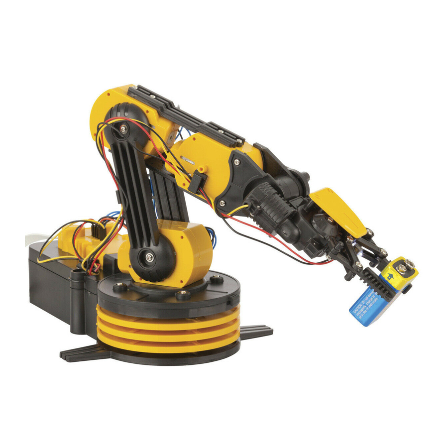
- Page 1 ROBOT ARM CONTROLLED BY CABLE-KIT C-9895...
-
Page 2: Table Of Contents
Contents ROBOT ARM: 1. Product Introduction 2. Tools You May Need 3. Mechanical Parts List 4. Plastic Parts 5. Mechanical Assembly Wired Control Box: 1. Product Introduction P.27 2. Tools You May Need P.27 3. Mechanical Parts List P.27 4. Plastic Parts P.28 5. -
Page 3: Robot Arm
ROBOT ARM ROBOT ARM ROBOT ARM Product Introduction: Learning basic robotic technology and build your own Wired Control Robot Arm with five motors and five joints. With its five-switch wired controller, the robot features base rotation, base, elbow and wrist motion, and a functional gripper. -
Page 4: Mechanical Parts List
Mechanical Parts List: Motor(M4.M5) Motor(M2.M3) Motor(M1) Orange Blue Yellow Black Black Black Gear 32/10T(Gray) Gear 32/10T(Brown) Gear 32T(Blue) Output Gear 10T(Black) Output Gear 10T(White) Round Shaft (2x20) Round Shaft Tapping Screw Tapping Screw (2.6x6) (2x16) (2.3x7) Machine Screw Tapping Screw Tapping Screw (2.6x10) (2.6x6) -
Page 5: Plastic Parts
Battery Terminal Battery Terminal Washer With Wire With Connector Sponge(Black) LED With Wire Wire Clip PC Board Plastic Parts:... - Page 6 Ignore...
-
Page 7: Mechanical Assembly
Mechanical Assembly: Gearbox Assembly For M4M 5 ¡ B P18x4 P5(Brown) (Gray) (Brown) (Gray) (Black) (Gray) P9x2 (Gray) (Blue) - Page 8 Black Orange P1x2 P13x3 Orange Black (M4좦M5)
- Page 9 Gearbox Assembly For M3 P18x4 P5(Brown) (Gray) (Brown) (Gray) (Black) (Gray) P9x2 (Gray) (Blue)
- Page 10 Black Blue P2x1 P13x3 Blue Black (M3)
- Page 11 Gearbox Assembly For M2 P18x4 P5(Brown) (Gray) (Brown) (Gray) (White) (Gray) P9x2 (Gray) (Blue)
- Page 12 Black Blue P2x1 P13x3 Blue Black (M2)
- Page 13 Blue “White“ Black Blue “Black“ Black Orange “Black“ Black Orange “Black“ Black B1x3 Black Orange B1x3 SIDE VIEW...
- Page 14 Orange Orange...
- Page 15 P13x3 Battery(D)x4...
- Page 16 P15x2 P19x2 Black Orange...
- Page 17 P12x4 P15x8 Black Blue Black Blue White Black Black Black Blue Blue Blue Black Black Blue...
- Page 18 P12x4 Black White F7x2 P14x4...
- Page 19 Gearbox Assembly For Gripper ( M1 ) P7(Black) P6(Blue) (Gray) (Gray) P5(Brown) P4(Gray) (Gray) (Brown)
- Page 20 Black Yellow P11x4...
- Page 22 P16x2...
- Page 24 E3x2 P14x4 P14x4 E3x2...
- Page 25 P13x3 Orange P12x3 Orange Black Black Orange Black Black Orange...
- Page 26 Wiring Right View Left View Black Black...
- Page 28 Finished Product...
-
Page 29: Wired Control Box
Wired Control Box Product Introduction: Using five levers to control the Robot Arm moves up and down, left and right, another on- off switch to control the search light. Connect with main unit by a 100cm flat cable. Tools You May Need: Long Nose Pliers Screwdriver Diagonal Cutter... -
Page 30: Plastic Parts
Plastic Parts : LIGHT Mechanical Assembly:... - Page 31 P2x5 P1x5 Finished Product P2x4...
- Page 32 Wiring Finished Product M3:Elbow Motion M2:Wrist Motion M1:Gripper Search Light M4:Base Motion M5:Base Rotation...
-
Page 33: How It Works
How it works: 1. Push any lever on the wired controller to start operation. 2. The different 12 movements of the Robot Arm as shown below: Gripper Wrist Motion Elbow Motion 0-1.77” Base Motion Search Light Base Rotation(1) Base Rotation(2) - Page 34 3.Working area: 4. All the five gearboxes equipped with safety gear, when the arm open, close, up or lower to the maximum position, and user keeps pushing the buttons, the safety gear will start to work to protect the gearbox and make 'da, da, da…' sound. 5.
-
Page 35: Trouble Shooting
Trouble shooting: 1. Ensure all wirings are correct.(Please refer on page 23,24 ) 41 44 2. If the Robot Arm does not have any response to the wired controller, please check if the 'BATTERY' and 'GND' connectors are in right position, and also if the batteries are placed in correct polarity.(Please refer on page 13 ) 3.If the Robot Arm moves wrong direction, please check if wiring of M1, M2, M3, M4,... - Page 36 Removal and replacement of batteries should be carried out by an adult or under adult supervision. Removal and replacement of batteries should be carried out by an adult or under adult supervision. Do not attempt to recharge non-rechargeable batteries. Rechargeable batteries must be removed Do not attempt to recharge non-rechargeable batteries.
- Page 37 Gearbox Assembly For Gripper ( M1 ) P7(Black) P6(Blue) (Gray) (Gray) P5(Brown) P4(Gray) (Gray) (Brown)
- Page 38 Black Yellow P11x4...
- Page 40 P16x2...
- Page 42 E3x2 P14x4 P14x4 E3x2...
- Page 43 P13x3 Orange P12x3 Orange Black Black Orange Black Black Orange...
- Page 44 Wiring Right View Left View Black Black...
- Page 46 Finished Product...
- Page 47 Wired Control Box Product Introduction: Using five levers to control the Robot Arm moves up and down, left and right, another on- off switch to control the search light. Connect with main unit by a 100cm flat cable. Tools You May Need: Long Nose Pliers Screwdriver Diagonal Cutter...
- Page 48 Plastic Parts : LIGHT Mechanical Assembly:...
- Page 49 P2x5 P1x5 Finished Product P2x4...
- Page 50 Wiring Finished Product M3:Elbow Motion M2:Wrist Motion M1:Gripper Search Light M4:Base Motion M5:Base Rotation...
- Page 51 How it works: 1. Push any lever on the wired controller to start operation. 2. The different 12 movements of the Robot Arm as shown below: Gripper Wrist Motion Elbow Motion 0-1.77” Base Motion Search Light Base Rotation(1) Base Rotation(2)
- Page 52 3.Working area: 4. All the five gearboxes equipped with safety gear, when the arm open, close, up or lower to the maximum position, and user keeps pushing the buttons, the safety gear will start to work to protect the gearbox and make 'da, da, da…' sound. 5.
- Page 53 Trouble shooting: 1. Ensure all wirings are correct.(Please refer on page 23,24 ) 41 44 2. If the Robot Arm does not have any response to the wired controller, please check if the 'BATTERY' and 'GND' connectors are in right position, and also if the batteries are placed in correct polarity.(Please refer on page 13 ) 3.If the Robot Arm moves wrong direction, please check if wiring of M1, M2, M3, M4,...
- Page 54 Gearbox Assembly For Gripper ( M1 ) P7(Black) P6(Blue) (Gray) (Gray) P5(Brown) P4(Gray) (Gray) (Brown)
- Page 55 Black Yellow P11x4...
- Page 57 P16x2...
- Page 59 E3x2 P14x4 P14x4 E3x2...
- Page 60 P13x3 Orange P12x3 Orange Black Black Orange Black Black Orange...
- Page 61 Wiring Right View Left View Black Black...
- Page 63 Finished Product...
- Page 64 Wired Control Box Product Introduction: Using five levers to control the Robot Arm moves up and down, left and right, another on- off switch to control the search light. Connect with main unit by a 100cm flat cable. Tools You May Need: Long Nose Pliers Screwdriver Diagonal Cutter...
- Page 65 Plastic Parts : LIGHT Mechanical Assembly:...
- Page 66 P2x5 P1x5 Finished Product P2x4...
- Page 67 Wiring Finished Product M3:Elbow Motion M2:Wrist Motion M1:Gripper Search Light M4:Base Motion M5:Base Rotation...
- Page 68 How it works: 1. Push any lever on the wired controller to start operation. 2. The different 12 movements of the Robot Arm as shown below: Gripper Wrist Motion Elbow Motion 0-1.77” Base Motion Search Light Base Rotation(1) Base Rotation(2)
- Page 69 3.Working area: 4. All the five gearboxes equipped with safety gear, when the arm open, close, up or lower to the maximum position, and user keeps pushing the buttons, the safety gear will start to work to protect the gearbox and make 'da, da, da…' sound. 5.
- Page 70 Trouble shooting: 1. Ensure all wirings are correct.(Please refer on page 23,24 ) 41 44 2. If the Robot Arm does not have any response to the wired controller, please check if the 'BATTERY' and 'GND' connectors are in right position, and also if the batteries are placed in correct polarity.(Please refer on page 13 ) 3.If the Robot Arm moves wrong direction, please check if wiring of M1, M2, M3, M4,...
- Page 71 Use of rechargeable batteries or mercury oxide batteries are not recommended for this product. Use of rechargeable batteries or mercury oxide batteries are not recommended for this product. NOTE. This kit is recommended for children aged 10 years, always escorted by an adult www.cebekit.com...
Need help?
Do you have a question about the C-9895 and is the answer not in the manual?
Questions and answers