Advertisement
Quick Links
Tools needed:
Kit Contents
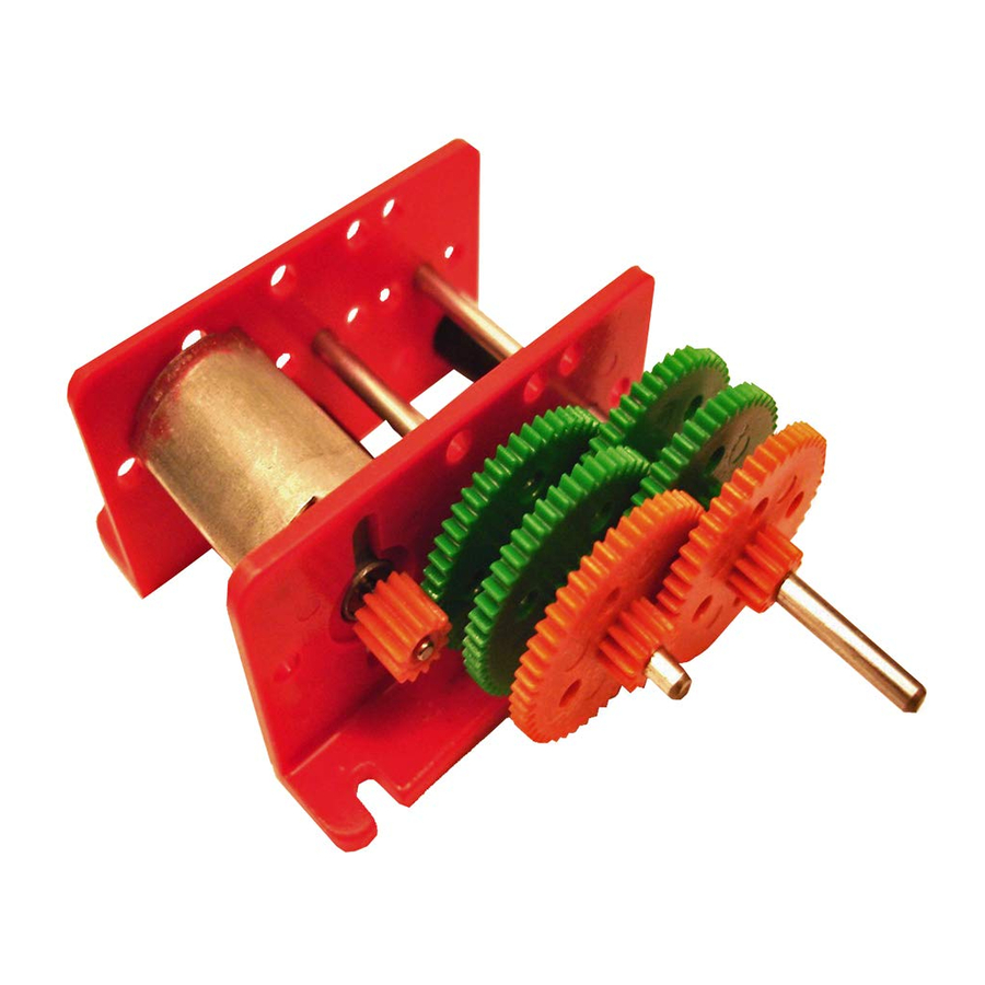
Kit to build a compact motor and gearbox, which provides an output speed very slow. The output shaft is Ø 3 mm and you can attach
any type of mechanical adaptation that is valid for the diameter .
Kit à construire un moteur compact et boîte de vitesses, qui fournit une sortie de vitesse très lente. L'arbre de sortie est Ø 3 mm et
peut être équipé tout type d'adaptation mécaniciens pour être valide pour que le diamètre (poulie, engrenage, etc) .. Il est conçu pour
de simples et économiques, éducatives, des modèles et les prototypes expérimentaux .
Kit para construir un grupo compacto de motor y caja reductora, que proporciona una velocidad de salida muy lenta. El eje de salida
es de Ø 3 mm y se le puede acoplar cualquier tipo de adaptación mecánica que sea válida para dicho diámetro
Screwdriver
Piece
Description
A
12V DC Motor
B
Pair of brackets, racks
C
Sprocket 12 teeth
D
Orange Double Gear 48/12
E
Double Gear 48/12 Green
F
Ø 3mm Shaft Length: 110mm
G
Ø 3mm Shaft Length: 70mm
H
Washer
I
Screw M3 x 40 mm
J
Black plastic spacers 30 mm
K
M3 nuts
L
Brass tube 5.5 mm
M
Tube brass 8 mm
Assembly Instructions
www.cebekit.es
Gear motor
Moto réducteur
Motor reductor
2 rpm 12V
TECHNICAL CHARACTERISTICS
Reduction 4096:1
Output speed of approximately 2 rpm@12VDC (*)
Voltage Motor: 4 a 12VDC (maximum 24V)
consumption: 0,03 - 0,1A
(*) may be affected by the friction of the shafts and gears.
Pliers
Unit
1
1
1
2
4
1
1
1
2
2
4
1
1
1
-
info@cebekit.com
C-8050
Advertisement

Related Manuals for Cebekit C-8050


Summary of Contents for Cebekit C-8050
- Page 1 Gear motor Moto réducteur Motor reductor 2 rpm 12V C-8050 TECHNICAL CHARACTERISTICS Reduction 4096:1 Output speed of approximately 2 rpm@12VDC (*) Voltage Motor: 4 a 12VDC (maximum 24V) consumption: 0,03 - 0,1A (*) may be affected by the friction of the shafts and gears.
- Page 2 C-8050 Insert the pinion pressure (C) in the Insert screws (I) into the holes indicated Details of the position correct engine. Mount between the racks (B), (*), then the spacers (J) and finally the terminals engine . as shown. nuts (K).
- Page 3 C-8050 Stagger the gears as shown the image, then insert the Secure the long axis (F) with washer retention (H), leaving a axes in holes indicated (*). gap ~ 0.5 mm to prevent friction. Décaler les engrenages comme le montre l'image, puis Fixez l'axe long (F) avec rondelle rétention (H), laissant un...
- Page 4 C-8050 - El motor quedará sujeto a presión al apretar las dos ultimas tuercas. Antes de apretarlas coloque el conjunto sobre una base plana, verifique que los terminales de conexión del motor quedan alojados en la ranura vertical y que todo está bien alineado.
Need help?
Do you have a question about the C-8050 and is the answer not in the manual?
Questions and answers