Table of Contents
Advertisement
Advertisement
Chapters
Table of Contents

Related Manuals for Omron SYSDRIVE 3G3XV-EV2 Series


Summary of Contents for Omron SYSDRIVE 3G3XV-EV2 Series
- Page 1 SYSDRIVE 3G3XV Inverter 3G3XV-jjjjj-EV2 Operation Manual Revised November 1997...
- Page 2 OMRON. No patent liability is assumed with respect to the use of the information contained herein. Moreover, because OMRON is constantly striving to improve its high-quality products, the information contained in this manual is subject to change without notice.
-
Page 3: Table Of Contents
TABLE OF CONTENTS SECTION 1 SYSDRIVE 3G3XV Inverter Main Unit ..1-1 Part Names of the 3G3XV ........1-2 Receiving . - Page 4 About this Manual: This manual provides operating procedures and parameter specifications for the SYS- DRIVE 3G3XV All-Digital Low-Noise Inverter. Section 1 describes handling, wiring, operation, and specifications of the SYSDRIVE 3G3XV series (hereinafter called 3G3XV). Section 2 outlines the digital operator performance,constants, operation, etc. Section 3 describes maintenance, periodic inspections, troubleshooting, etc.
- Page 5 SECTION 1 SYSDRIVE 3G3XV Inverter Main Unit This section describes handling, wiring, operation, and specifications of the SYSDRIVE 3G3XV series. 1-1 Part Names of the 3G3XV ........1-2 Receiving .
-
Page 6: Part Names Of The 3G3Xv
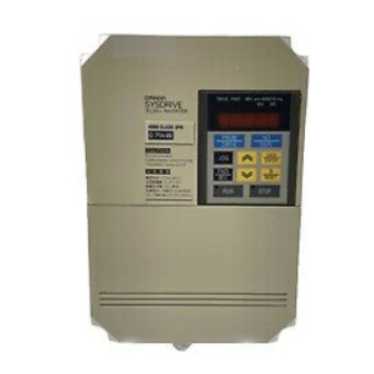
Section 1-2 Receiving Part Names of the 3G3XV The following diagram shows the main components of the SYS- DRIVE 3G3XV. The terminal block cover has been removed to expose the terminal blocks. Refer to 1-4-1 Terminal Blocks for details on removing the terminal block cover. Digital Operator (Model 3G3XV-PJVOP110) Set the operating constants with the... -
Page 7: Installation
Section 1-3 Installation Inverter Model Numbers 3G3XV-A4002-EV2 Country EV2: European countries (E: Old model) 3G3XV-series None:Japan Max. Applicable Motor Capacity 001: 0.1 kW 002: 0.2 kW 004: 0.4 kW 037: 3.7 kW Voltage Class 2: 3-phase, 200 V 4: 3-phase, 400 V B: Single-phase, 200 V Protective Structure A: Enclosed wall mounting... -
Page 8: Mounting Space
Section 1-3 Installation Protected from direct sunlight. Protected from corrosive gases or liquids. Free from airborne dust or metallic particles. Free from vibration. Free from magnetic noise. Caution To house multiple SYSDRIVE 3G3XVs in a switchgear, install a cooling fan or some other means to cool the air entering the Inverter below 113 F (45 C). -
Page 9: Wiring
Section 1-4 Wiring H1 H Four, d dia. Voltage Phase Max. Applicable Motor Output HP (kW) 200 V 3-phase 0.13 to 0.5 (0.1 to 0.4) 4.13 3.66 5.91 5.43 3.94 0.20 (105) (93) (150) (138) (100) 1/2 (0.75/1.5) 5.51 5.04 5.91 5.43 5.43... - Page 10 Section 1-4 Wiring Terminal Position The main circuit and control circuit terminal blocks are shown below. Terminal numbers are usually shown on the terminal num- ber nameplate, but the terminal numbers are printed on the printed board on some Inverters. Fault signal output terminal (FLT–...
-
Page 11: Standard Wiring Diagram
Section 1-4 Wiring 1-4-2 Standard Wiring Diagram Models with Digital Operators can be operated from the Digital Operator only by main circuit wiring. When these models are oper- ated by control circuit terminals, control constant change is required. For details refer to 2-8-2 Operation Mode Selection . Models without Digital Operator (with blind cover) are preset in Operation Mode from control circuit terminals at the factory prior to shipping. -
Page 12: Main Circuit
Section 1-4 Wiring 4. When using optional braking resistor (3G3IV- PERF150WJ), place a thermal overload relay between the braking resistor and Inverter to prevent the braking resistor from overheating. In addition, use a sequencer to break the power supply side on the thermal overload relay trip contact. 1-4-3 Main Circuit Main Circuit Wiring Connect wiring as shown below. - Page 13 200 to 230 V Large-size magnetic contactors DCR2-50A22E 250 VAC, 0.1 µF + 100 Ω Control relay DCR2-10A25C LY-2, -3 (OMRON) MM-2, -4 (OMRON) 1,000 VDC, 0.5 µF + 220 Ω 400- to 460-V Units DCR2-50D100B Note Made by MARCON Electronics. Marketed in Japan.
- Page 14 Section 1-4 Wiring Wiring Main Circuit Input/Output Phase rotation of input terminals L1 (R), L2 (S), L3 (T) is available in either direction, clockwise and counterclockwise. When Inverter output terminals T1 (U), T2 (V), and T3 (W) are connected to motor terminals T1 (U), T2 (V), and T3 (W), respec- tively, motor rotates counterclockwise, viewed from opposite drive end, upon forward operation command.
- Page 15 Section 1-4 Wiring Wire Sizes and Types 200-V-class 3-phase Input Series: Wire size Circuit Model Inverter Terminal symbol Terminal Wire type 3G3XV 3G3XV capacity screw Main A2001 Power cable: 0.3 kVA L1 (R), L2 (S), L3 (T), B1/ , 14-10 2 to 5.5 circuit 600 V B2, T1 (U), T2 (V), T3 (W)
- Page 16 Section 1-4 Wiring Circuit Circuit Model Model Inverter Inverter Terminal symbol Terminal symbol Terminal Terminal Wire size Wire type Wire type 3G3XV 3G3XV capacity capacity screw screw Main AB015 Power cable: 2.5 kVA L1 (R), L2 (S), B1/ , B2, T1 14-10 2 to 5.5 circuit (U), T2 (V), T3 (W)
- Page 17 Section 1-4 Wiring Caution Observe the following guidelines when wiring. Lead size should be determined considering voltage drop of leads. Select the lead size so that the voltage drop will be within 2% of the normal rated voltage. The voltage drop can be obtained from the lead resistance (R) in Ω/km, wiring distance (D) in meters, and current (I) in A using the following equation: –3...
-
Page 18: Control Circuit
Section 1-4 Wiring 1-4-4 Control Circuit Control Circuit Wiring The control signals are connected by screws. The following figure shows the relationship between I/O signals (factory preset values) and screw terminal numbers. The terminal functions shown in the figure indicate standard setting prior to shipping. Since Operation Mode from the Digital Operator is set for the Model with the Digital Operator, it is necessary to change the control constants when operation is performed from the control circuit terminals. - Page 19 Section 1-4 Wiring Control Circuit (Terminals Factory Preset) Control Circuit Terminal Functions Classification Terminal Signal name Function Signal level Sequence Photo-coupler Forward run/stop signal Forward run when “closed”, Input Signal stop when “open”. insulation input 24 VDC 8 mA Reverse run/stop signal Reverse run when “closed”, stop when “open”.
-
Page 20: Operation
Section 1-5 Operation Precautions for Control Circuit Wiring Take the following precautions when wiring. 1, 2, 3... 1. Separate the control signal line from power lines. Otherwise a malfunction might occur. 2. For the frequency setting signal (analog), use a shielded lead and be sure that the signal is terminated properly. -
Page 21: Setting Before Operation
Section 1-5 Operation 1-5-2 Setting Before Operation Since the standard Inverter Models are shipped with the default values listed in 2-7 Function/Constant List , the Digital Operator must be used in order to change the constants from the initial val- ues to values in accordance with the load specifications. -
Page 22: Test Run Method
Section 1-5 Operation V/f Characteristics: The figure below shows the output voltage for Inverter output fre- quency. When its characteristic (max. voltage/frequency) differs from that of the optimum motor, refer to 2-8-3 V/f Characteristic Setting . Output voltage Output freq. (Hz) Motor Rated Current Since the Inverter is provided with electronic thermal overload pro- Setting... - Page 23 Section 1-5 Operation 3. Set the frequency value using the Up and Down Arrow Keys or the RESET Key. 4. Press the DATA/ENTER Key to enter the frequency value. 5. Press the RUN Key. 6. To stop, press the STOP Key. Operation Using Control Circuit Terminal Inputs In this Mode, the Inverter is operated by a frequency setter and/or operation switches connected to the control circuit terminal.
- Page 24 Section 1-5 Operation Precautions The motor does not start up if both FWD and REV run signals are turned on simultaneously. If they are turned on simultaneously during run, the motor decelerates to a stop. When output frequency reaches 1.5 Hz (set value prior to ship- ping) at deceleration, the dynamic brake (DB) operates for 0.5 s and metallic noise is generated by the motor.
-
Page 25: Specifications
Section 1-6 Specifications Specifications 1-6-1 200-V-class Specifications 3-phase A2001 A2002 A2004 A2007 A2015 A2022 A2037 Inverter Model 3G3XV jjjjj EV2 3G3XV-jjjjj-EV2 Single-phase AB001 AB002 AB004 AB007 AB015 AB022 AB037 Max. applicable motor output Hp (kW) 0.13 0.25 2 (1.5) 3 (2.2) 5 (3.7) (see note 1) (0.1) - Page 26 Section 1-6 Specifications Inverter Model Inverter Model 3-phase A2001 A2002 A2004 A2007 A2015 A2022 A2037 3G3XV-jjjjj-EV2 3G3XV-jjjjj-EV2 Single-phase AB001 AB002 AB004 AB007 AB015 AB022 AB037 Operation Input Operation signal Forward operation/reverse operation by individual command conditions di i signals Reset Releases protection while the function is operating.
-
Page 27: 400-V-Class Specifications
Section 1-6 Specifications 1-6-2 400-V-class Specifications Inverter Model 3G3XV-jjjjj-EV2 A4002 A4004 A4007 A4015 A4022 A4037 Max. applicable motor output Hp (kW) 0.25 (0.2) 0.5 (0.4) 1 (0.75) 2 (1.5) 3 (2.2) 5 (3.7) Output char- Inverter capacity (kVA) acteristics Rated output current (A) Max. -
Page 28: Optional Units
Section 1-6 Specifications Inverter Model 3G3XV-jjjjj-EV2 A4002 A4004 A4007 A4015 A4022 A4037 Operation Input Operation signal Forward operation/reverse operation by individual command conditions di i signals Reset Releases protection while the function is operating. Multifunction input Multifunction contact input: two of the following signals avail- selection able to select. -
Page 29: Peripheral Units
Section 1-6 Specifications 1-6-4 Peripheral Units Name Model (code no.) Function Radio noise 3G3IV-PHFjjjjjj Use a line filter to reduce radio frequency interference. Always protective filter use at the input side of the Inverter. 3G3IV-PLFjjjj Isolator K3FK Isolates the Inverter input and output signals to reduce induced noise. -
Page 30: Digital Operator
SECTION 2 Digital Operator This section outlines the Digital Operator performance, constants, and operation. 2-1 Digital Operator Components ........2-2 Function/Constant Setting . -
Page 31: Digital Operator Components
Section 2-1 Digital Operator Components Digital Operator Components Red indicator lights Red indicator lights Red indicator lights by external during FWD run during REV run. terminal commands. SEQ: When RUN/STOP signal is used. REF: When frequency ref. Red indicator lights is used. -
Page 32: Function/Constant Setting
Section 2-2 Function/Constant Setting Function/Constant Setting DRIVE Mode and PRGM (Program) Mode Selection of DRIVE Mode or PRGM Mode can be performed by PRGM using the Key when the Inverter is stopped. When function DRIVE selection or a change of set value is required, switch to the PRGM Mode. -
Page 33: Function/Constant Setting
Section 2-2 Function/Constant Setting Reading and Setting The 3G3XV has various functions for optimum operation. Use it Constants with the set values according to the load conditions or operation conditions of the matching machine. Set values are read or set by the Digital Operator. -
Page 34: Digital Operator Operation Example
Section 2-3 Digital Operator Operation Example Precautions on In the following cases, the set value blinks for 3 s and the data Constant Setting before changing is returned. When a value exceeding the setting range is set Set values of constants No. 32 and No. 33 are not in descending order. -
Page 35: Digital Operator Operation Example
Section 2-3 Digital Operator Operation Example [Description] [Key operation] [Digital Operator display] Operation Turn on Frequency reference power supply. value is displayed. Select output frequency FWD JOG monitor display. (optional) DSPL Select rotating direction. Indicator lights. (FWD is default on power on.) Jog operation. -
Page 36: Constant Initialization And Write-Protection
Section 2-4 Constant Initialization and Write-protection Constant Initialization and Write-protection 2-4-1 Constant Initialization This operation returns the values of all constants to their original factory settings. To initialize constants, write 8 to constant No. 00. Description Key Operation Digital Operator Display PRGM Select PRGM Mode. -
Page 37: Corrective Function
Section 2-5 Corrective Function Corrective Function 2-5-1 Adjustment of Frequency Setting Value, Output Frequency Bias (No. 23) and Gain (No. 22) Any desired value of output frequency for frequency set value (0 to 10 V or 4 to 20 mA) can be set. Example Adjust so as to obtain 10% speed (6 Hz) at frequency setting volt- age 0 V and 100% speed (60 Hz) at 8 V. -
Page 38: Monitor
Section 2-6 Monitor 2-5-2 Calibration of Frequency Meter Calibration of frequency meter or ammeter connected to the Inverter can be performed even without providing a calibration resistor. Example When the frequency meter specifications are 3 V and 1 mA scale, operation is performed at 60 Hz with a frequency setting voltage of 10 V. -
Page 39: Monitor
Section 2-6 Monitor Key Operation Frequency reference DSPL value display Output frequency If a fault occurs, the DSPL monitor display contents are displayed. Output current DSPL monitor display Fault reset RESET No.-jj reading DSPL Monitoring of Fault Contents If a fault occurs, the fault contents are displayed with priority over other display items. -
Page 40: Function/Constant List
Section 2-7 Function/Constant List Function/Constant List First Functions (Constant Nos. 0 to 19) Function Name Description Initial User setting page values Password Password 0: Password (No. 00) setting/reading and setting first function (constant Nos. 1 to 19) reading possible Constant 1: First function (constant Nos. -
Page 41: Function/Constant List
Section 2-7 Function/Constant List Function Name Description Initial User setting page values V/f char- Minimum out- Setting unit: 0.1 Hz, setting range; 0.1 to 1.5 Hz acteristic put frequency 10 Hz setting Minimum out- Setting unit: 0.1 V, setting range: 0.1 to 50 12.0 V put frequency (Note 1) - Page 42 Section 2-7 Function/Constant List (0.4 kW) and standard motor 200 V 60 Hz. 0.4 kW are com- bined. Set the values described in the motor nameplate.
- Page 43 Section 2-7 Function/Constant List Second Functions (Constant Nos. 20 to 29) Function Name Description Initial User set- page ting values 0000 REV run pro- Run signal digit = 0: REV run enabled hibit selection 2 = 1: REV run disabled Operator digit = 0: STOP Key effective digit...
- Page 44 Section 2-7 Function/Constant List Third Functions (Constant Nos. 30 to 49) Function Name Description Initial User setting Page values Stall Prevention 30 Level of stall Setting unit: 1%, setting range 30% to 170% preventive 200% operation Note: Stall prevention is not performed during during acceleration when 200% is set.
- Page 45 Section 2-7 Function/Constant List Function Name Description Initial User setting Page values Multi- Photo- Multifunction 0: Running func- coupler input selec- 1: Frequency coincidence tion output tion 1 (termi- 2: Zero speed selec- signal nal 13 func- 3: Frequency detection (output frequency tion tion selec- frequency detection level)
- Page 46 Section 2-7 Function/Constant List Function Name Description Initial User setting Page values Function setting 46 Operation digit = 0: Operation stopped by 0110 selection momentary power loss after detection momentary = 1: Operation continues after power loss momentary power loss Enable/Dis- digit = 0: Read only able setting...
-
Page 47: Description Of Functions And Constants
Section 2-8 Description of Functions and Constants Function Name Description Initial User setting Page values Speed search Speed Setting unit: 1%, setting range: 0 to 200 150% control search deactivation current level Min. base- Setting unit: 0.1 s, setting range: 0.0 to 0.5 s block time V/F during... -
Page 48: Operation Mode Selection
Section 2-8 Description of Functions and Constants Constant no. 00 value Function Initializes all control constants. Terminal functions are returned to the initial factory settings. Initializes all control constants. Terminal functions are 3-wire sequence. For details, refer to 2-8-14 Multifunction Contact Input Function Selection . 2-8-2 Operation Mode Selection Item name... - Page 49 Section 2-8 Description of Functions and Constants In addition, any desired V/f pattern can be set for special specifica- tions. Any V/f pattern can be set according to the load characteristics. The factory preset value is set to 60 Hz saturation type pattern. Voltage Voltage (See note 1.)
-
Page 50: 4-Step Speed Change
Section 2-8 Description of Functions and Constants 2-8-4 4-step Speed Change Item name Constant to be set Factory preset Multi-speed frequency command No. 13 to No. 16 0.0 Hz for both Multi-function command No. 32 and No. 33 No. 32 =1, No. 33 = 3 Up to 4 steps of speeds can be set using signals from external ter- minals 4 and 5. -
Page 51: Accel/Decel Time And Patterns
Section 2-8 Description of Functions and Constants 2-8-6 Accel/Decel Time and Patterns Item name Constant to be set Factory preset Acceleration time 1 No. 9 10.0 s Deceleration time 1 No. 10 10.0 s Acceleration time 2 No. 11 10.0 s Deceleration time 2 No. -
Page 52: Electronic Thermal Overload Function
Section 2-8 Description of Functions and Constants 2-8-8 Electronic Thermal Overload Function Item name Constant to be set Factory preset Motor type No. 18 0000 Motor rated current No. 19 1.9 A (for A2004) Motor output current is monitored by the Inverter’s built-in elec- tronic thermal overload function to prevent Inverter exclusive-use motors or standard motors from overloading. -
Page 53: Output Frequency Limit
Section 2-8 Description of Functions and Constants 2-8-10 Output Frequency Limit Item name Constant to be set Factory preset Frequency (speed) command upper limit No. 24 100% Frequency (speed) command lower limit No. 25 The upper and lower limits for the output frequency can be clamped. -
Page 54: Motor Stall Prevention Function
Section 2-8 Description of Functions and Constants 2-8-12 Motor Stall Prevention Function Item name Constant to be set Factory preset Operation level for stall prevention during No. 30 170% acceleration Operation level for stall prevention during run- No. 31 160% ning Stall prevention during deceleration No. -
Page 55: Full-Range Automatic Torque Boost
Section 2-8 Description of Functions and Constants The operation level is lowered according to the following calcula- tion. OP1= OP2 x VF/OF OP1: Stall prevention operation level during acceleration in the constant power output area OP2: Stall prevention operation level during acceleration (No. 30) VF: Maximum voltage frequency (No. -
Page 56: Multifunction Contact Input Function Selection
Section 2-8 Description of Functions and Constants 2-8-14 Multifunction Contact Input Function Selection Item name Constant to be set Factory preset Multifunction contact input function No. 32 and No. 33 No. 32 =1, No. 33 = 3 The function of external output terminals 4 and 5 can be changed if necessary. - Page 57 Section 2-8 Description of Functions and Constants UP/DOWN Command This command is used to increase or decrease the Inverter’s fre- quency using the sequence input. FWD/STOP REV/STOP DOWN Note When No. 33 is set to ”14” UP/DOWN command, the UP command will be allocated to terminal 4 and the settings of No.
-
Page 58: Multifunction Output Function
Section 2-8 Description of Functions and Constants 2-8-15 Multifunction Output Function Item name Constant to be set Factory preset Multifunction output function No. 34 and No. 35 No. 34 = 0, No. 35 = 1 Constants No. 34 and No. 35 determine the functions of external output terminals 13 and 14, respectively. -
Page 59: Overtorque Detection Function
Section 2-8 Description of Functions and Constants 2-8-17 Overtorque Detection Function Item name Constant to be set Factory preset Overtorque detection level No. 38 160% Overtorque detection time No. 39 0.1 s Overtorque detection signal No. 34 and No. 35 No. -
Page 60: Carrier Frequency
Section 2-8 Description of Functions and Constants 2-8-18 Carrier Frequency Item name Constant to be set Factory preset Carrier frequency upper limit No. 40 Changing the carrier frequency reduces RFI noise and leakage current without increasing motor noise. Carrier frequency (kHz) = 2.5 kHz constant No. -
Page 61: S-Curve At Accel/Decel Time
Section 2-8 Description of Functions and Constants Set Value = 3: Set Value or More Release width –2 Hz No. 36 Output frequency Closed Frequency detection signal 2-8-20 S-curve at Accel/Decel Time Item name Constant to be set Factory preset S-curve at accel/decel time No. -
Page 62: Other Functions
Section 2-8 Description of Functions and Constants Note S-curve characteristics time refers to the time from acceleration rate 0 to the time when a normal acceleration rate determined by a specified acceleration time is obtained. Time chart at FWD/REV run change with S-curve characteris- tics: The figure below shows the time chart at FWD/REV run change during deceleration and stop. -
Page 63: Enable/Disable Setting Constants In Drive Mode
Section 2-8 Description of Functions and Constants Note 0.75 kW max.: Approximately 1 s. 1.5 kW max.: Approximately 2 s. Enable/Disable Setting Digit 2 = 0: Constant setting is disabled during running Constants in DRIVE Digit 2 = 1: Constant setting is enabled during running Mode (no-09 to no-17, no-22, no-23, no-29, no-45 are enabled) Selection Level of Stall... -
Page 64: Speed Search Function
Section 2-8 Description of Functions and Constants Set the range of setting prohibit frequency in the units of 0.1 Hz. The range of the setting prohibit frequency is determined as fol- lows, depending on combinations with No. 50 to No. 52. No. - Page 65 Section 2-8 Description of Functions and Constants Set value = 10: Speed search starts with the frequency reference value when search command is input. FWD(REV) RUN com- 0.5 sec. or less mand SEARCH command Speed synchronization detection Max. frequency or fre- quency ref.
-
Page 66: Accel/Decel Prohibit Function
Section 2-8 Description of Functions and Constants When momentary power loss time is longer than the minimum baseblock time, speed search operation is started immediately after power recovery. When min. baseblock When min. baseblock time is longer than time is shorter than momentary power loss momentary power loss time. -
Page 67: Slip Compensation Speed Control
Section 2-8 Description of Functions and Constants Note When the FWD (REV) run command is input in the status where the accel/decel prohibit command is input, the baseblock status is continued and the motor does not operate. The motor will operate at the frequency set in constant No. 25 (fre- quency lower limit) when No. -
Page 68: Inverter Overload Protection
Section 2-8 Description of Functions and Constants 2. The slip compensation function does not work if the Inverter is in regenerative operation. 3. The slip compensation function dows not work if 0.0 is set for the electronic thermal reference current. no-59 = Set to a small value if the response is slow and adjust to a large value if vibration occurs. -
Page 69: Troubleshooting And Maintenance
SECTION 3 Troubleshooting and Maintenance This section describes troubleshooting, inspection, and maintenance procedures. 3-1 Fault Display ..........3-1-1 Protection Functions . - Page 70 Section 3-1 Fault Display Fault Display 3-1-1 Protection Functions Protection function Explanation Monitor Fault con- display tact output uU1 (UV1) Main When the Inverter power voltage drops, torque Operation voltage circuit becomes insufficient and motor is overheated. Inverter protection voltage output is stopped when the main circuit DC voltage becomes lower than the low voltage detection level for 15 ms or longer.
- Page 71 Section 3-1 Fault Display Protection func- Error causes Action to be taken tion Main Inverter capacity is too small. Check the power capacity and power sys- voltage circuit Voltage drop due to wiring. tem. protec- voltage A motor of large capacity (11 kW or UV display appears when the Inverter power tion greater) connected to the same power...
- Page 72 Section 3-1 Fault Display 3-1-2 Warning and Self-diagnosis Functions Protection function Explanation Monitor Fault con- display tact output Low-voltage protection Monitor display appears when the main circuit DC (UV) (main circuit voltage voltage drops under the detection level while the (Blink) operation insufficient)
- Page 73 Section 3-2 Correcting Motor Faults Protection function Error causes Action to be taken Low-voltage protection Input voltage drop Check the input power supply voltage (main circuit voltage using a tester. If the voltage is low, insufficient) adjust the input voltage. Overtorque detection Motor current exceeded the set value Check the driven machine and correct...
-
Page 74: Maintenance
Section 3-3 Maintenance Fault Possible Cause Corrective Action Motor rotates, but Wiring of frequency setting circuit is incor- Correct the wiring. variable speed rect. does not work. Load is too large. Reduce the load. Motor speed is Motor ratings (number of poles, voltage) Check motor specifications and name- too high (low) are incorrect. - Page 75 Section 3-3 Maintenance 2. The equipment is normal if the insulation resistance tester indi- cating 1 MΩ or more. 3G3XV 2‘ (R)(S)(T)(U)(V)(W) Caution Do not conduct a high voltage test on the control circuit terminals. 3-3-3 Installing/Removing the Digital Operator Follow the procedures below to install or remove the Digital Opera- tor.
- Page 76 Section 3-3 Maintenance 2. Press the lever down (3) and insert a standard screwdriver in slot A, as shown below, then lift the operator up (4) and out of the Inverter. Operator Lever...
-
Page 77: Revision History
Revision History A manual revision code appears as a suffix to the catalog number on the front cover of the manual. Cat. No. I005-E1-2 Revision code The following table outlines the changes made to the manual during each revision. Page numbers refer to the previous version.
Need help?
Do you have a question about the SYSDRIVE 3G3XV-EV2 Series and is the answer not in the manual?
Questions and answers