
Subscribe to Our Youtube Channel
Related Manuals for KSB Hya-Solo DV


Summary of Contents for KSB Hya-Solo DV
- Page 1 Pressure Booster System Hya-Solo DV From series 2014w33 Installation/Operating Manual...
- Page 2 Legal information/Copyright Installation/Operating Manual Hya-Solo DV Original operating manual All rights reserved. The contents provided herein must neither be distributed, copied, reproduced, edited or processed for any other purpose, nor otherwise transmitted, published or made available to a third party without the manufacturer's express written consent.
-
Page 3: Table Of Contents
Installing unpressurised inlet tanks ............... 21 Fitting the dry running protection device ............ 22 Connection to power supply ................22 Commissioning/Start-up/Shutdown ...........24 Commissioning/start-up ................. 24 Switching on the pressure booster system ............ 25 Check list for commissioning/start-up ............25 Hya-Solo DV 3 of 54... - Page 4 Adjusting the settings ..................34 Servicing/Maintenance ...............41 General information/Safety regulations ............41 Servicing/inspection ..................42 Trouble-shooting ................44 10.1 Hya-Solo DV ....................44 10.2 PumpDrive ....................... 45 Related Documents ................47 11.1 List of components ..................47 EC Declaration of Conformity ............49 Certificate of Decontamination ............50...
-
Page 5: Glossary
Certificate of decontamination operated directly on mains power, independ- ently of the control unit. A certificate of decontamination is enclosed by the customer when returning the product to the manufacturer to certify that the product Hya-Solo DV 5 of 54... -
Page 6: General
The series/serial number uniquely identifies the pressure booster system and serves as identification for all further business processes. In the event of damage, immediately contact your nearest KSB service centre to maintain the right to claim under warranty. Noise characteristics see (⇨ Section 5.6 Page 13) 1.2 Installation of partly completed machinery... -
Page 7: Safety
In conjunction with one of the signal words this symbol indicates a hazard involving electrical voltage and identifies information about protection against electrical voltage. Machine damage In conjunction with the signal word CAUTION this symbol indicates a hazard for the machine and its functions. Hya-Solo DV 7 of 54... -
Page 8: Software Changes
The software has been specially created for this product and thoroughly tested. It is impermissible to make any changes or additions to the software or parts of the software. Software updates supplied by KSB are excluded from this rule. Hya-Solo DV... -
Page 9: Transport/Temporary Storage/Disposal
On transfer of goods, check each packaging unit for damage. In the event of in-transit damage, assess the exact damage, document it and no- tify KSB or the supplying dealer (as applicable) and the insurer about the dam- age in writing immediately. -
Page 10: Return To Supplier
(⇨ Section 13 Page 50) Always indicate any safety and decontamination measures taken. NOTE If required, a blank certificate of decontamination can be downloaded from the KSB web site at: www.ksb.com/certificate_of_decontamination 4.5 Disposal WARNING Fluids, consumables and supplies which are hot and/or pose a health hazard Hazard to persons and the environment! ▷... -
Page 11: Description
5 Description 5 Description 5.1 General description ▪ Pressure booster system 5.2 Designation Example: Hya-Solo DV / 04 05 / 2 - 4 Table 4: Key to the designation Code Description Hya-Solo Pressure booster system with one pump Model with three-phase motor, speed-controlled, pres-... -
Page 12: Configuration And Function
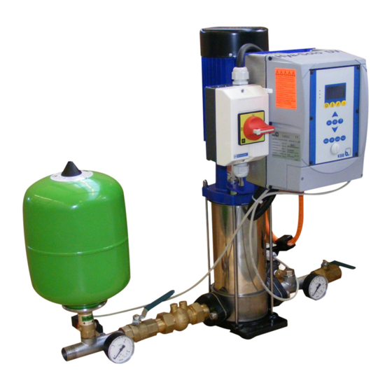
5 Description The PumpDrive speed control system is mounted on and ready-wired to the pump set. The system comes with separate rubber anti-vibration pads. 5.5 Configuration and function Fig. 3: Hya-Solo DV Master switch Accumulator Pump Pressure transmitter PumpDrive Valves... -
Page 13: Noise Characteristics
The PumpDrive is wired to the master switch, the motor and the pressure sensor at the factory. Work at the power terminals is only required if the PumpDrive needs to be removed. The power terminals are located underneath the V-shaped cover. Hya-Solo DV 13 of 54... - Page 14 1.2 Nm to ensure that the device has IP55 enclosure protection. DANGER Open terminals and connectors of brake resistor. Danger to life! ▷ Do not open the terminals and connectors of the brake resistor. Hya-Solo DV 14 of 54...
- Page 15 Fig. 4: Power supply and motor wiring up to 7.5 kW Analog input 2 Brake resistor +24VIN 0 PE L1 1 2 3 4 5 6 Fig. 5: Power supply and motor wiring from 11 kW Analog input 2 Brake resistor Hya-Solo DV 15 of 54...
- Page 16 Table 6: Max. cable cross-sections to be connected to control terminals Control termi- Rigid and flexible cables Flexible cable with wire end sleeve nals Terminal strip 0.2 - 1.5 mm 0.75 mm Terminal strip 0.2 - 2.5 mm 0.25 - 1.5 mm Hya-Solo DV 16 of 54...
- Page 17 SB1 + CAN signal SB1 - CAN signal PE (GROUND) Ground PE (GROUND) Ground SB1-GND Ground for CAN SB1 + CAN signal SB1 - CAN signal SB1Z- Bus terminator for CAN SB1Z+ Bus terminator for CAN Hya-Solo DV 17 of 54...
- Page 18 (250 V AC, 1 A) COM2 NO contact "COM" No. 2 (250 V AC, 1 A) NO contact "NO" No. 1 (250 V AC, 1 A) COM1 NO contact "COM" No. 1 (250 V AC, 1 A) Hya-Solo DV 18 of 54...
-
Page 19: Installation At Site
NOTE Do not install pressure booster systems next to sleeping or living quarters. If expansion joints (KSB accessory) are used for damping vibrations, their fatigue strength (endurance limit) must be given due consideration. Expansion joints must be installed to allow quick and easy replacement. -
Page 20: Installing The Piping
▷ Take suitable precautions to protect the expansion joint if any welding work is carried out nearby. CAUTION Leaking expansion joint Flooding of installation room! ▷ Regularly check for cracks or blisters, exposed fabric or other defects. Hya-Solo DV 20 of 54... -
Page 21: Installing Unpressurised Inlet Tanks
Install the closed PE inlet tank (under atmospheric pressure) available as a KSB acces- sory as described in the installation instructions supplied with the tank. -
Page 22: Fitting The Dry Running Protection Device
External ON/OFF input. The functions of digital inputs 2 to 5 can be parameterised by the user at the control panel. To connect the inputs use terminal P4-13 (+24 V DC). If an external 24 V DC Hya-Solo DV 22 of 54... - Page 23 ▪ Pump input power Further details and parameters can be found in the LON literature for PumpDrive; re- fer to the Product Catalogue on the KSB web site. The LON literature is based on the LONMARK Functional Profile Pump Controller V 1.0 - SFPTpumpController standard.
-
Page 24: Commissioning/Start-Up/Shutdown
In accordance with DIN EN 806, prior to commissioning, the pressure booster system must be flushed by the operator and disinfected, if necessary. Commissioning should be carried out by specialist KSB staff. CAUTION Foreign matter in the piping Damage to the pump/pressure booster system! ▷... -
Page 25: Switching On The Pressure Booster System
Prime and vent the pressure booster system from the inlet side. Check inlet pressure. Check whether all cables are still firmly connected to the terminals inside the control unit. Check the setpoint, re-adjust if necessary. Hya-Solo DV 25 of 54... -
Page 26: Shutdown
As long as the pressure booster system is out of operation, water is supplied directly at p through the pressure booster system. Set the master switch to "0". NOTE Drain the pressure booster system for prolonged shutdown. Hya-Solo DV 26 of 54... -
Page 27: Operating The Pressure Booster System
The display shows important information for operating the pressure booster system. Plain-text data can be accessed and parameters can be set. 4070:0007 Fig. 8: PumpDrive control panel Display "Traffic light" LEDs Function keys Navigation keys Operating keys Service interface Hya-Solo DV 27 of 54... - Page 28 Red: One or more than one alert is active Amber: One or more than one warning is active Green: Trouble-free operation 8.1.3 Function keys You can use the menu keys to access the elements at the first menu level directly. Hya-Solo DV 28 of 54...
- Page 29 Switches off the pressure booster system. Automatic operation Auto Switches the pressure booster system to automatic mode. Parameterisable function key Func Without function on Hya-Solo DV pressure booster sys- tems. Hya-Solo DV 29 of 54...
-
Page 30: Menu Structure
The pressure booster system can be parameterised by using the Service-Tool soft- ware. The control unit can also be updated via this interface. 8.2 Menu structure Table 15: Structure of main menu: KSB logo/actual value display Main menu key Sub-menu Information displayed... -
Page 31: Access Levels
The first digit of the parameter number indicates the first menu level, which is called up directly via the four function keys. Table 16: Function keys Operation Diagnosis Settings Information Hya-Solo DV 31 of 54... -
Page 32: Monitoring
Table 17: Function keys To diplay current messages, choose the Diagnosis menu and then 2-2-1 (warnings) or 2-3-1 (alerts). Active warnings and alerts can also be connected to the relay outputs. (⇨ Section 8.7.5 Page 38) Hya-Solo DV 32 of 54... -
Page 33: Description Of Parameters
HHHH:MM Hours (H) and minutes (M) since alert has gone 8.6 Description of parameters The main parameters required for operating Hya-Solo DV are described below. For an overview and detailed information on all PumpDrive parameters please refer to the enclosed PumpDrive operating manual. -
Page 34: Adjusting The Settings
The PI controller of the frequency inverter is optimised when leaving the factory, therefore no changes are required. Should a process-related adjustment of the PI controller be necessary, check/change the factory settings in accordance with the following table: Hya-Solo DV 34 of 54... - Page 35 1 – Constant pressure/differential pressure at the sensor measuring location 2 – Variable pressure/differential pressure activates the dynamic pressure com- pensation function 3-9-1-6 Automatic controller recognition when a signal is connected to the actual val- ue source Hya-Solo DV 35 of 54...
- Page 36 8 Operating the Pressure Booster System 8.7.3 Changing the stop criteria Hya-Solo DV with PumpDrive recognises whether the flow rate supplied is actually used. When the system has reached its steady state (the actual value has reached the set- point within the programmed hysteresis for pressure fluctuations 5), PumpDrive in- creases the setpoint by a value 3 (test pulse) for a period of time 2.
- Page 37 Table 23: The functions of inputs 2 to 5 are user-definable: Parameter Description Factory settings Setting range / options Access 3-7-1-2 Function of digital input 2 7 See selection list Customer 3-7-1-3 Function of digital input 3 10 See selection list Customer Hya-Solo DV 37 of 54...
- Page 38 Factory setting Setting range / op- Access tions 3-8-2-1 Setting of analog input 1 See selection list Customer 3-8-2-2 Analog IN 1 Low voltage 0..3-8-2-3 [V] Customer 3-8-2-3 Analog IN 1 High voltage 3-8-2-2..10 [V] Customer Hya-Solo DV 38 of 54...
- Page 39 Source 2 Source 3 Source 4 Parameter Description Factory settings Setting range / op- Access tions 3-8-4-1 Source 1 for Analog OUT See selection list Customer 3-8-4-2 Source 2 for Analog OUT See selection list Customer Hya-Solo DV 39 of 54...
- Page 40 If the system has been commissioned/started up before, restoring the factory set- tings will cause all parameter settings made so far to be deleted if they have not been backed up using the Service software. Hya-Solo DV 40 of 54...
-
Page 41: Servicing/Maintenance
A regular maintenance schedule will help avoid expensive repairs and contribute to trouble-free, reliable operation of the pressure booster system with a minimum of maintenance expenditure and work. Never use force when dismantling and re-assembling the pressure booster system. Hya-Solo DV 41 of 54... -
Page 42: Servicing/Inspection
9.1.1 Inspection contract For all inspection and servicing work to be carried out at regular intervals we recom- mend taking out the inspection contract offered by KSB. Contact your Service Partner for details. Checklist for commissioning/inspection and maintenance 9.2 Servicing/inspection 9.2.1... - Page 43 = 2 bar: pre-charge pressure 2 x 0.8 = 1.6 bar start CAUTION Pre-charge pressure too high Damage to accumulator! ▷ Observe data provided by accumulator manufacturer (see name plate or operat- ing manual of accumulator). Hya-Solo DV 43 of 54...
-
Page 44: Trouble-Shooting
Non-compliance will lead to forfeiture of any and all rights to claims for damages. If problems occur that are not described in the following table, consultation with KSB’s customer service is required. Pressure booster system cuts out. Pressure fluctuations on the discharge side. -
Page 45: Pumpdrive
Interchange two phases of the tion of rotation. power cable. ✘ ✘ ✘ ✘ - Inlet pressure lower than stated in Connect inlet tank, contact KSB. the purchase order ✘ ✘ ✘ ✘ - Water extraction higher than sta- Contact KSB. - Page 46 ✘ Sensor (signal) fault Check the sensor and sensor cable. The pump pressure must be released before attempting to remedy faults on parts which are subjected to pressure. Discon- nect the pump from the power supply! Hya-Solo DV 46 of 54...
-
Page 47: Related Documents
82-1 79-2 743.02 743.01 743.01 Fig. 15: General assembly drawing of Hya-Solo DV with Movitec 2, 4, 6, 10, 15 Table 31: Spare parts for Hya-Solo DV with Movitec 2, 4, 6, 10, 15 Part No. Description Ident. No. Accumulator... - Page 48 Hya-Solo DV with Movitec 25, 40, 60, 90 82-1 79-2 Fig. 16: General assembly drawing of Hya-Solo DV with Movitec 25, 40, 60, 90 Table 32: Spare parts for Hya-Solo DV with Movitec 25, 40, 60, 90 Part No. Description Ident.
-
Page 49: Ec Declaration Of Conformity
67227 Frankenthal (Germany) The manufacturer herewith declares that the product: Hya-Solo DV KSB order number: ....................▪ is in conformity with the provisions of the following Directives as amended from time to time: – Pump set: Machinery Directive 2006/42/EC – Pump set: Electromagnetic Compatibility Directive 2004/108/EC The manufacturer also declares that ▪... -
Page 50: Certificate Of Decontamination
We confirm that the above data and information are correct and complete and that dispatch is effected in accordance with the relevant legal provisions....................................Place, date and signature Address Company stamp Required fields Hya-Solo DV 50 of 54... -
Page 51: Commissioning Report
14 Commissioning Report 14 Commissioning Report The KSB pressure booster system specified below was today commissioned by the undersigned authorised KSB customer service engineer who created this report. Pressure booster system details Type series ............................Size ............................Serial number ............................ -
Page 52: Index
Partly completed machinery 6 Faults Causes and remedies 44, 46 Return to supplier 10 Installation at site 19 Safety 7 Scope of supply 13 Setpoint LEDs 28 Setting the setpoint 32 List of spare parts 47, 48 Hya-Solo DV 52 of 54... - Page 54 KSB Aktiengesellschaft 67225 Frankenthal • Johann-Klein-Str. 9 • 67227 Frankenthal (Germany) Tel. +49 6233 86-0 • Fax +49 6233 86-3401 www.ksb.com...
Need help?
Do you have a question about the Hya-Solo DV and is the answer not in the manual?
Questions and answers