
Related Manuals for BCM EMS-TGL

Summary of Contents for BCM EMS-TGL
- Page 1 EMS-TGL Intel 11th Gen Intel®Core™ Processor i7/i5/i3 Fanless Rugged Embedded System Quick Reference Guide Ed –07 May 2021 Copyright Notice Copyright 2021, ALL RIGHTS RESERVED. Part No. E2017AAO0A1R...
- Page 2 For the most frequently asked questions, you can easily find answers in your product documentation. These answers are normally a lot more detailed than the ones we can give over the phone. So please consult the user’s manual first. 2 EMS-TGL Series Quick Reference Guide...
-
Page 3: Table Of Contents
System Dimensions ..................... 19 1.5.1 EMS-TGL Front & Top view ....................... 19 1.5.2 EMS-TGL-6 COM/EMS-TGL-4 COM Isolation Front & Top view ..........20 1.5.3 EMS-TGL-6 LAN/EMS-TGL-PSE Front & Top view ..............21 1.5.4 EMS-TGL-HDMI Front & Top view .................... 22 1.5.5... - Page 4 SMBUS of TCA9555 address setting (OJP1) ................ 50 2.11 EBM-CDVS DB-A Connector settings ..............50 2.11.1 Front Panel Connector 1 (CN1) ..................... 50 2.12 Installing Hard Disk & Memory (EMS-TGL) ............51 3.BIOS Setup ........................52 Introduction ......................53 Starting Setup ...................... 53 Using Setup ......................
- Page 5 3.6.3.2.1.5 PCI Express Root Port 10 (IET) ................79 3.6.3.2.1.6 PCI Express Root Port 11 (M.2 KeyB)..............80 3.6.3.2.1.7 PCI Express Root Port 12 (M.2 KeyE)..............81 3.6.3.2.2 SATA And RST Configuration ................... 82 3.6.3.2.3 HD Audio Configuration ....................82 EMS-TGL Series Quick Reference Guide...
- Page 6 4. Drivers Installation ....................... 89 Install Chipset Driver ................... 90 Install ME Driver ....................91 Install VGA Driver ....................92 Install Audio Driver (For Realtek ALC888S) ............93 Install SerialIO Driver ................... 94 Install Ethernet Driver ..................95 6 EMS-TGL Series Quick Reference Guide...
-
Page 7: Getting Started
1.2 Packing List 1 x EMS-TGL 11th Gen Intel®Core™ Processor i7/i5/i3 Fanless Rugged Embedded System 1 x Terminal block to lockable DC Jack cable ... -
Page 8: System Specifications
1 x M.2 Key-M 2242/2280, support PCIe Gen. IV x 4 (NVMe SSD) Combination 1 x M.2 Key-B 2242, support SATA (share with expansion slot) Edge I/O USB Port 2 x USB 3.1 Gen.2 (10Gbp/s) 8 EMS-TGL Series Quick Reference Guide... - Page 9 Ethernet Interface 1 x 10/100/1000Base-Tx GbE compatible. 2.5G LAN Port (i225-LM) ACT/LINK SPEED Definition Definition LED Signal Light Off No Link Solid Orange 2.5G Solid Yellow Connection Solid Green 1G/100M Flashing Activity Light Off EMS-TGL Series Quick Reference Guide...
- Page 10 3. Sweep:1 Oct/ per one minute. (logarithmic) Vibration Test (non-operation) 4. Test Axis : X,Y and Z axisTest time :30 min. each axis 5. System condition : Non-Operating mode 6. Reference IEC 60068-2-6 Testing procedures 10 EMS-TGL Series Quick Reference Guide...
- Page 11 1 x HDMI, 2 x RJ45, 2 x RS-232/422/485 (BIOS), 2 x USB 2.0 EBM-BYTS DB-A AUX-M01 4 x RS-232/422/485(BIOS), 2 x USB 2.0 AUX-M07 4 x RS-232/422/485(BIOS) w/ 2.5KV isolation, 2 x USB 2.0 Note: Specifications are subject to change without notice. EMS-TGL Series Quick Reference Guide 11...
-
Page 12: System Overview
EMS-TGL 1.4 System Overview 1.4.1 Front View EMS-TGL EMS-TGL-6 COM/EMS-TGL-6 LAN/EMS-TGL-PSE/EMS-TGL-4 COM Isolation /EMS-TGL-HDMI/EMS-TGL-DVI/EMS-TGL-USB 1.4.2 Rear View EMS-TGL 12 EMS-TGL Series Quick Reference Guide... - Page 13 Quick Reference Guide EMS-TGL-6 COM/EMS-TGL-4 COM Isolation EMS-TGL-6 LAN/EMS-TGL-PSE EMS-TGL-HDMI EMS-TGL Series Quick Reference Guide 13...
- Page 14 System power indicator Reset Reset button HDD indicator WWAN WWAN Indicator WLAN WLAN Indicator COM1/2 Serial port connector 1/2 GPIO General purpose I/O connector EX PWR Power on button Mic-in Mic-in audio jack Line-out Line-out jack 14 EMS-TGL Series Quick Reference Guide...
- Page 15 2 x USB 2.0 connector RJ-45 Ethernet 1/2 LAN1/2 DC-in DC power-in connector EMS-TGL-6 LAN/EMS-TGL-PSE Connectors Label Function Note System power indicator Power Reset Reset button HDD indicator WWAN WWAN Indicator WLAN Indicator WLAN EMS-TGL Series Quick Reference Guide 15...
- Page 16 USB 3.1 Gen.1 2 x USB 3.1 Gen.1 connector USB 3.1 Gen.2 2 x USB 3.1 Gen.2 connector USB 2.0 2 x USB 2.0 connector RJ-45 Ethernet 1/2/3/4 LAN1/2/3/4 DC-in DC power-in connector EMS-TGL-DVI Connectors 16 EMS-TGL Series Quick Reference Guide...
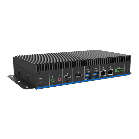
- Page 17 Serial port connector 1/2 GPIO General purpose I/O connector EX PWR Power on button Mic-in Mic-in audio jack Line-out jack Line-out HDMI 2 x HDMI connector DP connector USB 3.1 Gen.1 6 x USB 3.1 Gen.1 connector EMS-TGL Series Quick Reference Guide 17...
- Page 18 EMS-TGL USB 3.1 Gen.2 2 x USB 3.1 Gen.2 connector 3 x USB 2.0 connector USB 2.0 LAN1/2 RJ-45 Ethernet 1/2 DVI connector DC-in DC power-in connector 18 EMS-TGL Series Quick Reference Guide...
-
Page 19: System Dimensions
Quick Reference Guide 1.5 System Dimensions 1.5.1 EMS-TGL Front & Top view (Unit: mm) EMS-TGL Series Quick Reference Guide 19... -
Page 20: Ems-Tgl-6 Com/Ems-Tgl-4 Com Isolation Front & Top View
EMS-TGL 1.5.2 EMS-TGL-6 COM/EMS-TGL-4 COM Isolation Front & Top view (Unit: mm) 20 EMS-TGL Series Quick Reference Guide... -
Page 21: Ems-Tgl-6 Lan/Ems-Tgl-Pse Front & Top View
Quick Reference Guide 1.5.3 EMS-TGL-6 LAN/EMS-TGL-PSE Front & Top view (Unit: mm) EMS-TGL Series Quick Reference Guide 21... -
Page 22: Ems-Tgl-Hdmi Front & Top View
EMS-TGL 1.5.4 EMS-TGL-HDMI Front & Top view (Unit: mm) 22 EMS-TGL Series Quick Reference Guide... -
Page 23: Ems-Tgl-Dvi Front & Top View
Quick Reference Guide 1.5.5 EMS-TGL-DVI Front & Top view (Unit: mm) EMS-TGL Series Quick Reference Guide 23... -
Page 24: Ems-Tgl-Usb Front & Top View
EMS-TGL 1.5.6 EMS-TGL-USB Front & Top view (Unit: mm) 24 EMS-TGL Series Quick Reference Guide... -
Page 25: Hardware Configuration
2. Hardware Configuration Jumper and Connector Setting, Driver and BIOS Installing For advanced information, please refer to: 1- EBM-TGLS, AUX-M01, AUX-M02, AUX-M04, AUX-M07, EBM-BYTS DB-A, EBM-CDVS DB-A and EBM-BYTS DB-E included in this manual. EMS-TGL Series Quick Reference Guide 25... -
Page 26: Ems-Tgl Connector Mapping
In RS-232 Mode Signal PIN PIN Signal NDCD# NDSR# NRXD NRTS# NTXD NCTS# NDTR# NRI# In RS-422 Mode Signal PIN PIN Signal TxD1- TxD1+ RxD1+ RxD1- In RS-485 Mode Signal PIN PIN Signal DATA1- DATA1+ 26 EMS-TGL Series Quick Reference Guide... -
Page 27: Serial Port 3/4/5/6 Connector (Com3/4/5/6)
NRXD NRTS# NTXD NCTS# NDTR# NRI# 2.1.3 General purpose I/O connector (GPIO) Signal Signal GPO1 GPI3 GPI1 GPO4 GPO2 GPI4 GPI2 GPO3 2.1.4 DC power-in connector (DC-in) Signal VIN + (BAT+) CHASSIS_GND VIN- (BAT-) EMS-TGL Series Quick Reference Guide 27... -
Page 28: Ebm-Tgls, Aux-M01, Aux-M02, Aux-M04, Aux-M07, Ebm-Byts Db-A
EMS-TGL 2.2 EBM-TGLS, AUX-M01, AUX-M02, AUX-M04, AUX-M07, EBM-BYTS DB-A, EBM-CDVS DB-A and EBM-BYTS DB-E Overviews 2.2.1 EBM-TGLS 28 EMS-TGL Series Quick Reference Guide... -
Page 29: Aux-M01
Quick Reference Guide 2.2.2 AUX-M01 2.2.3 AUX-M02 EMS-TGL Series Quick Reference Guide 29... -
Page 30: Aux-M04
EMS-TGL 2.2.4 AUX-M04 2.2.5 AUX-M07 30 EMS-TGL Series Quick Reference Guide... -
Page 31: Ebm-Byts Db-A
Quick Reference Guide 2.2.6 EBM-BYTS DB-A 2.2.7 EBM-CDVS DB-A EMS-TGL Series Quick Reference Guide 31... -
Page 32: Ebm-Byts Db-E
EMS-TGL 2.2.8 EBM-BYTS DB-E 32 EMS-TGL Series Quick Reference Guide... -
Page 33: Ebm-Tgls Jumper & Connector List
2 x DDR4 SODIMM connector IET_CB1 IET Expansion slot JLPC1 LPC port connector 7 x 2 header, pitch 2.00 mm JSPI1 SPI connector 4 x 2 header, pitch 2.00 mm DP connector NGFF2 M.2 KEY-E 2230 connector EMS-TGL Series Quick Reference Guide 33... - Page 34 DCOUT1 DC Output connector 6 x 1 wafer, pitch 2.50 mm 1 x 3 terminal block, pitch 5.08 DC Input connector JVIN1 JEC_ROM1 EC Debug connector 5 x 2 header, pitch 2.00 mm 34 EMS-TGL Series Quick Reference Guide...
-
Page 35: Ebm-Tgls Jumpers & Connectors Settings
2.4 EBM-TGLS Jumpers & Connectors settings 2.4.1 Multi-function select (SW1) Power mode ATX* DDI2 mode(DP+) DisplayPort* HDMI Cable select 2.4.2 Serial port 1/2 pin 9 signal select (JRI1/2) JRI1 Ring* JRI2 +12V * Default EMS-TGL Series Quick Reference Guide 35... -
Page 36: Serial Port 1/2 Rs-232/422/485 Mode Select (Jcom_Sel1/2)
EMS-TGL 2.4.3 Serial port 1/2 RS-232/422/485 mode select (JCOM_SEL1/2) RS-232* JCOM_SEL1 JCOM_SEL2 RS-422/ 485 *Default 2.4.4 Clear CMOS (JBAT1) Protect * Clear CMOS *Default 36 EMS-TGL Series Quick Reference Guide... -
Page 37: Lpc Port Connector (Jlpc1)
2.4.5 LPC port connector (JLPC1) Signal PIN PIN Signal LPC_AD0 +3.3V LPC_AD1 IET_RST# LPC_AD2 LPC_LFRAME# LPC_AD3 CLK_24M_80 LPC_SERIRQ +5VSB 2.4.6 SPI connector (JSPI1) Signal PIN PIN Signal BIOS_WP# BIOS_HOLD# SPI0_BIOS_MOSI SPI0_BIOS_MISO SPI0_BIOS_CLK SPI0_CS0# +3.3VSB EMS-TGL Series Quick Reference Guide 37... -
Page 38: Front Panel Connector (Jfp1)
EMS-TGL 2.4.7 Front Panel Connector (JFP1) Signal PWR_LED- +5VSB PM_SYSRST# PWRBTN_IN# 2.4.8 DC Output connector (DCOUT1) Signal +VIN +VIN +VIN 38 EMS-TGL Series Quick Reference Guide... -
Page 39: Dc Input Connector (Jvin1)
Quick Reference Guide 2.4.9 DC Input connector (JVIN1) Signal +DC_IN CHASSIS_GND 2.4.10 EC Debug connector (JEC_ROM1) Signal Signal +VSPI_EC EC_FSCE# EC_FSCK EC_FMISO EC_FMOSI EC_HOLD# EC_SMCLK_DEBUG EC_SMDAT_DEBUG EMS-TGL Series Quick Reference Guide 39... -
Page 40: On-Board Header For Usb2.0 (Jusb1)
EMS-TGL 2.4.11 On-board header for USB2.0 (JUSB1) Signal Signal +5VSB +5VSB USB2_R_DN5 USB2_R_DN4 USB2_R_DP5 USB2_R_DP4 2.4.12 Power on/off connector (PWRBTN1) Signal PWRBTN#_R 40 EMS-TGL Series Quick Reference Guide... -
Page 41: Aux-M01, Aux-M02, Aux-M04, Aux-M07, Ebm-Byts Db-A, Ebm-Cdvs Db-A And Ebm-Byts Db-E Jumper & Connector List
3 x 2 header, pitch 2.00mm Connectors Label Function Note ZUSB1~2 USB connector 1~2 LAN2~5 LAN connector 2~5 Power connector 6 x 1 wafer, pitch 2.00mm ZPWR1 Z_JLANLED LAN ACT/LNK/SPD LED 8 x 2 wafer, pitch 2.00mm EMS-TGL Series Quick Reference Guide 41... - Page 42 USB connector 1~2 Front Panel connector 1 5 x 1 wafer, pitch 2.00 mm DVI1 DVI connector 2.5.7 EBM-BYTS DB-E Connectors Label Function Note 3 x USB2.0 connector USB1~3 USB4~7 4 x USB3.0 connector 42 EMS-TGL Series Quick Reference Guide...
-
Page 43: Aux-M01 Jumpers & Connectors Settings
Quick Reference Guide 2.6 AUX-M01 Jumpers & Connectors settings 2.6.1 COM 3/4/5/6 pin 9 signal select (JRI3/4/5/6) Ring* JRI6 JRI5 +12V JRI4 JRI3 * Default 2.6.2 USB connector (USB3) Signal PUSBP3 PUSBN3 PV5A_USB3 EMS-TGL Series Quick Reference Guide 43... -
Page 44: Usb Connector (Jusb3)
EMS-TGL 2.6.3 USB connector (JUSB3) Signal PUSBP3 PUSBN3 PV5A_USB3 2.6.4 SMBUS of TCA9555 address setting (PJP1) Signal PIN PIN Signal MC_9555A0 MC_9555A1 MC_9555A2 44 EMS-TGL Series Quick Reference Guide... -
Page 45: Aux-M02 Connectors Settings
Z_LAN_LED_100#_1 Z_LAN_LED_ACT_3 Z_LAN_LED_ACT_1 +3.3VSB +3.3VSB Z_LAN_LED_1000#_4 Z_LAN_LED_1000#_2 Z_LAN_LED_100#_4 Z_LAN_LED_100#_2 Z_LAN_LED_ACT_4 Z_LAN_LED_ACT_2 +3.3VSB +3.3VSB 2.7.2 Normal/Bypass mode LED (JLANMODE) Signal PIN PIN Signal Z_RC5_LAN23-STA Z_RC7_LAN45-STA Z_+VLED Z_+VLED Z_RA4_LAN23-BYP Z_RA1_LAN45-BYP Z_+VLED Z_+VLED Z_RC6_LAN23-NOR Z_RC4_LAN45-NOR Z_+VLED Z_+VLED EMS-TGL Series Quick Reference Guide 45... -
Page 46: Aux-M04 Jumpers & Connectors Settings
EMS-TGL 2.8 AUX-M04 Jumpers & Connectors settings 2.8.1 Operating Modes select (ZJP1) Normal Auto* Reset * Default 2.8.2 Power connector (ZPWR1) Signal +V12-28V +V12-28V +V12-28V 46 EMS-TGL Series Quick Reference Guide... -
Page 47: Lan Act/Lnk/Spd Led (Z_Jlanled)
Quick Reference Guide 2.8.3 LAN ACT/LNK/SPD LED (Z_JLANLED) Signal PIN PIN Signal Z_LAN_LED_1000#_3 15 16 Z_LAN_LED_1000#_1 Z_LAN_LED_100#_3 Z_LAN_LED_100#_1 Z_LAN_LED_ACT_3 Z_LAN_LED_ACT_1 +3.3VSB +3.3VSB Z_LAN_LED_1000#_4 Z_LAN_LED_1000#_2 Z_LAN_LED_100#_4 Z_LAN_LED_100#_2 Z_LAN_LED_ACT_4 Z_LAN_LED_ACT_2 +3.3VSB +3.3VSB EMS-TGL Series Quick Reference Guide 47... -
Page 48: Aux-M07 Connector Settings
EMS-TGL 2.9 AUX-M07 Connector settings 2.9.1 SMBUS of TCA9555 address setting (SJP2) Signal PIN PIN Signal SMC_9555A0 SMC_9555A1 SMC_9555A2 48 EMS-TGL Series Quick Reference Guide... -
Page 49: Ebm-Byts Db-A Jumpers & Connectors Settings
Auto Direction RTS# Control* 485TXP external OPEN* biasing resistor 485TXN external OPEN* biasing resistor In Serial Port 2 mode Auto Direction RTS# Control* 485TXP external 9-10 OPEN* biasing resistor 485TXN external 11-12 OPEN* biasing resistor EMS-TGL Series Quick Reference Guide 49... -
Page 50: Smbus Of Tca9555 Address Setting (Ojp1)
EMS-TGL 2.10.3 SMBUS of TCA9555 address setting (OJP1) Signal PIN PIN Signal MC_9555A0 MC_9555A1 MC_9555A2 2.11 EBM-CDVS DB-A Connector settings 2.11.1 Front Panel Connector 1 (CN1) Signal SYSRST# SATA_LED# PWRSB_LED- 50 EMS-TGL Series Quick Reference Guide... -
Page 51: Installing Hard Disk & Memory (Ems-Tgl)
Quick Reference Guide 2.12 Installing Hard Disk & Memory (EMS-TGL) Step 1. Remove 8 screws from the bottom of your system and take it off. Step 2. Slide the DDR4 SODIMM into the memory socket and press it down until properly seated. -
Page 52: Bios Setup
EMS-TGL 3.BIOS Setup 52 EMS-TGL Series Quick Reference Guide... -
Page 53: Introduction
If you do not press the keys at the correct time and the system does not boot, an error message will be displayed and you will again be asked to. Press F1 to Continue, DEL to enter SETUP EMS-TGL Series Quick Reference Guide 53... -
Page 54: Using Setup
Note: Some of the navigation keys differ from one screen to another. To Display a Sub Menu Use the arrow keys to move the cursor to the sub menu you want. Then press <Enter>. A “” pointer marks all sub menus. 54 EMS-TGL Series Quick Reference Guide... -
Page 55: Getting Help
BIOS Vendor and your systems manufacturer to provide the absolute maximum performance and reliability. Even a seemingly small change to the chipset setup has the potential for causing you to use the override. EMS-TGL Series Quick Reference Guide 55... -
Page 56: Bios Setup
<Enter> to accept and enter the sub-menu. 3.6.1 Main Menu This section allows you to record some basic hardware configurations in your computer and set the system clock. 56 EMS-TGL Series Quick Reference Guide... -
Page 57: System Language
3.6.2 Advanced Menu This section allows you to configure your CPU and other system devices for basic operation through the following sub-menus. EMS-TGL Series Quick Reference Guide 57... -
Page 58: Cpu Configuration
Options Description When enabled, a VMM can utilize the additional Intel(VMX) Virtualization Disabled hardware capabilities provided by Vanderpool Technology Enabled[Default] Technology. All[Default] Active Processor Cores Number of cores to enable in each processor package. 58 EMS-TGL Series Quick Reference Guide... -
Page 59: Power & Performance
Allows more than two frequency ranges to be Intel® SpeedSted™ Disabled supported. Enable/Disable Intel® Speed Shift Technology Intel® Speed Shift Enabled[Default], support. Enabling will expose the CPPC v2 interface to Technology Disabled allow for hardware controlled P-states. EMS-TGL Series Quick Reference Guide 59... -
Page 60: Pch-Fw Configuration
C states to go to C states when it’s not 100% utilized. Disabled 3.6.2.3 PCH-FW Configuration 3.6.2.3.1 Firmware Update Configuration Item Option Description Enabled Enable/Disable Me FW Image Re-Flash Me FW Image Re-Flash Disabled[Default], function. 60 EMS-TGL Series Quick Reference Guide... -
Page 61: Trusted Computing
Options Description Enables or Disables BIOS support for security Disable Security Device Support device. O.S. will not show Security Device. TCG EFI Enable[Default] protocol and INT1A interface will not be available. 3.6.2.5 APCI Settings EMS-TGL Series Quick Reference Guide 61... -
Page 62: It8528 Super Io Configuration
Set Parameters of Serial Port 3 (COMC). Serial Port 4 Configuration Set Parameters of Serial Port 4 (COMD). Serial Port 5 Configuration Set Parameters of Serial Port 5 (COME). Serial Port 6 Configuration Set Parameters of Serial Port 5 (COMF). 62 EMS-TGL Series Quick Reference Guide... -
Page 63: Serial Port 1 Configuration
Item Option Description Enabled[Default], Serial Port Enable or Disable Serial Port (COM). Disabled UART 232[Default] UART 232 422 485 UART 422 Change the Serial Port as RS232/422/485. UART 485 3.6.2.6.2 Serial Port 2 Configuration EMS-TGL Series Quick Reference Guide 63... -
Page 64: Serial Port 3 Configuration
UART 232(LOOPBACK) UART 232[Default] Change the Serial Port as UART 232 422 485 UART 422 RS232/422/485. UART 485 Enabled, 422/485 termination TERM from GPIO. Disabled[Default] 10M bps Slew limiting SLEW from GPIO. 250k bps[Default] 64 EMS-TGL Series Quick Reference Guide... -
Page 65: Serial Port 4 Configuration
UART 232(LOOPBACK) UART 232[Default] Change the Serial Port as UART 232 422 485 UART 422 RS232/422/485. UART 485 Enabled, 422/485 termination TERM from GPIO. Disabled[Default] 10M bps Slew limiting SLEW from GPIO. 250k bps[Default] EMS-TGL Series Quick Reference Guide 65... -
Page 66: Serial Port 5 Configuration
UART 232(LOOPBACK) UART 232[Default] Change the Serial Port as UART 232 422 485 UART 422 RS232/422/485. UART 485 Enabled, 422/485 termination TERM from GPIO. Disabled[Default] 10M bps Slew limiting SLEW from GPIO. 250k bps[Default] 66 EMS-TGL Series Quick Reference Guide... -
Page 67: Serial Port 6 Configuration
UART 232(LOOPBACK) UART 232[Default] Change the Serial Port as UART 232 422 485 UART 422 RS232/422/485. UART 485 Enabled, 422/485 termination TERM from GPIO. Disabled[Default] 10M bps Slew limiting SLEW from GPIO. 250k bps[Default] EMS-TGL Series Quick Reference Guide 67... -
Page 68: H/W Monitor
Enable or disable System wake on alarm event. Select Disabled[Default], Fixed Time, system will wake on the hr::min::sec specified. Wake system from S5 Fixed Time Select Dynamic Time, System will wake on the current time Dynamic Time + Increase minute(s). 68 EMS-TGL Series Quick Reference Guide... -
Page 69: Serial Port Console Redirection
Quick Reference Guide 3.6.2.9 Serial Port Console Redirection Item Options Description Disabled[Default], Console Redirection Console Redirection Enable or Disable. Enabled Disabled[Default], Console Redirection EMS Console Redirection Enable or Disable. Enabled 3.6.2.9.1 Legacy Console Redirection Settings EMS-TGL Series Quick Reference Guide 69... -
Page 70: Usb Configuration
Floppy enumerates devices according to their media JetFlashTranscend 8GB 1100 Forced FDD format. Optical drives are emulated as ‘CDROM’, drives with no media will be Hard Disk CD-ROM emulated according to a drive type. 70 EMS-TGL Series Quick Reference Guide... -
Page 71: Network Stack Configuration
Quick Reference Guide 3.6.2.11 Network Stack Configuration Item Options Description Enabled Network Stack Enable/Disable UEFI Network Stack. Disabled[Default] 3.6.2.12 NVMe Configuration EMS-TGL Series Quick Reference Guide 71... -
Page 72: Chipset
EMS-TGL 3.6.3 Chipset 3.6.3.1 System Agent (SA) Configuration Item Option Description Enabled[Default] VT-d VT-d capability. Disabled 72 EMS-TGL Series Quick Reference Guide... -
Page 73: Memory Configuration
Quick Reference Guide 3.6.3.1.1 Memory Configuration 3.6.3.1.2 Graphics Configuration Item Option Description Select which of IGFX/PEG/PCI Graphics Auto[Default] Primary Display device should be Primary Display Or select IGFX HG for Hybrid Gfx. EMS-TGL Series Quick Reference Guide 73... -
Page 74: Pch-Io Configuration
EMS-TGL 3.6.3.2 PCH-IO Configuration Item Option Description Disabled PCH LAN Controller Enable or disable onboard NIC. Enabled[Default] 3.6.3.2.1 PCI Express Configuration 74 EMS-TGL Series Quick Reference Guide... -
Page 75: Pci Express Root Port 5 (Iet)
L0s State AUTO – BIOS auto ASPM configure DISABLE – Disables ASPM. L0sL1 Auto Disabled L1 Substates L1.1 PCI Express L1 Substates settings. L1.1 & L1.2[Default], Auto[Default] Gen1 PCIe Speed Configure PCIe speed. Gen2 Gen3 EMS-TGL Series Quick Reference Guide 75... -
Page 76: Pci Express Root Port 6 (Iet)
L0s State AUTO – BIOS auto ASPM configure DISABLE – Disables ASPM. L0sL1 Auto Disabled L1 Substates L1.1 PCI Express L1 Substates settings. L1.1 & L1.2[Default], Auto[Default] Gen1 PCIe Speed Configure PCIe speed. Gen2 Gen3 76 EMS-TGL Series Quick Reference Guide... -
Page 77: Pci Express Root Port 8 (I225)
L0s State AUTO – BIOS auto ASPM configure DISABLE – Disables ASPM. L0sL1 Auto Disabled L1 Substates L1.1 PCI Express L1 Substates settings. L1.1 & L1.2[Default], Auto[Default] Gen1 PCIe Speed Configure PCIe speed. Gen2 Gen3 EMS-TGL Series Quick Reference Guide 77... -
Page 78: Pci Express Root Port 9 (Iet)
L0s State AUTO – BIOS auto ASPM configure DISABLE – Disables ASPM. L0sL1 Auto Disabled L1 Substates L1.1 PCI Express L1 Substates settings. L1.1 & L1.2[Default], Auto[Default] Gen1 PCIe Speed Configure PCIe speed. Gen2 Gen3 78 EMS-TGL Series Quick Reference Guide... -
Page 79: Pci Express Root Port 10 (Iet)
L0s State AUTO – BIOS auto ASPM configure DISABLE – Disables ASPM. L0sL1 Auto Disabled L1 Substates L1.1 PCI Express L1 Substates settings. L1.1 & L1.2[Default], Auto[Default] Gen1 PCIe Speed Configure PCIe speed. Gen2 Gen3 EMS-TGL Series Quick Reference Guide 79... -
Page 80: Pci Express Root Port 11 (M.2 Keyb)
Force all links to L0s State AUTO – ASPM BIOS auto configure DISABLE – L0sL1 Disables ASPM. Auto Disabled L1 Substates L1.1 PCI Express L1 Substates settings. L1.1 & L1.2[Default], Auto[Default] Gen1 PCIe Speed Configure PCIe speed. Gen2 Gen3 80 EMS-TGL Series Quick Reference Guide... -
Page 81: Pci Express Root Port 12 (M.2 Keye)
Force all links to L0s State AUTO – ASPM BIOS auto configure DISABLE – L0sL1 Disables ASPM. Auto Disabled L1 Substates L1.1 PCI Express L1 Substates settings. L1.1 & L1.2[Default], Auto[Default] Gen1 PCIe Speed Configure PCIe speed. Gen2 Gen3 EMS-TGL Series Quick Reference Guide 81... -
Page 82: Sata And Rst Configuration
EMS-TGL 3.6.3.2.2 SATA And RST Configuration Item Option Description Enabled[Default] SATA Controller(s) Enable/Disable SATA Device. Disabled, Enabled[Default] Port 0 Enable or Disable SATA Port. Disabled, 3.6.3.2.3 HD Audio Configuration 82 EMS-TGL Series Quick Reference Guide... -
Page 83: Board & Panel Configuration
40 sec 50 sec Watch Dog Select WatchDog. 1 min 2 min 10 min 30 min Disabled Enable/Disabled USB Standby Power USB Standby Power Enabled[Default] during S3/S4/S5. Disabled[Default] SHOW DMI INFO SHOW DMI INFO. Enabled EMS-TGL Series Quick Reference Guide 83... -
Page 84: Security
EMS-TGL 3.6.4 Security Administrator Password Set setup Administrator Password User Password Set User Password 84 EMS-TGL Series Quick Reference Guide... -
Page 85: Secure Boot Menu
User mode with enrolled Platform Key(PK) 2.CSM Enabled[Default] function is disabled. Customizable Secure Boot mode: In Custom mode Standard[Default] Secure Boot Mode Secure Boot Policy variables can be configured by a Custom physically present user without full authentication. EMS-TGL Series Quick Reference Guide 85... -
Page 86: Boot
1~ 65535 activation key. 65535(0xFFFF) means indefinite waiting. On[Default] Bootup NumLock State Select the Keyboard NumLock state Disabled[Default] Quiet Boot Enables or disables Quiet Boot option Enabled Boot Option #1 Set the system boot order. 86 EMS-TGL Series Quick Reference Guide... -
Page 87: Save And Exit
Reset the system after saving the changes. 3.6.6.2 Discard Changes and Reset Any changes made to BIOS settings during this session of the BIOS setup program are discarded. The setup program then exits and reboots the controller. EMS-TGL Series Quick Reference Guide 87... -
Page 88: Restore Defaults
This option restores all BIOS settings to the factory default. This option is useful if the controller exhibits unpredictable behavior due to an incorrect or inappropriate BIOS setting. 3.6.6.4 Launch EFI Shell from filesystem device Attempts to Launch EFI Shell application (Shellx64.efi) from one of the available filesystem devices. 88 EMS-TGL Series Quick Reference Guide... -
Page 89: Drivers Installation
Quick Reference Guide 4. Drivers Installation Note: Installation procedures and screen shots in this section are for your reference and may not be exactly the same as shown on your screen. EMS-TGL Series Quick Reference Guide 89... -
Page 90: Install Chipset Driver
Windows 10 operation system. If the warning message appears while the installation process, click Continue to go on. Step 3. Click Install. Step1. Click Next. Step 4. Click Finish to complete setup. Step 2. Click Accept. 90 EMS-TGL Series Quick Reference Guide... -
Page 91: Install Me Driver
Continue to go on. Step 3. Click Next to proceed setup. Step1. Click Next to start installation. Step 4. Click Finish to complete setup. Step 2. Click Next. EMS-TGL Series Quick Reference Guide 91... -
Page 92: Install Vga Driver
Windows 10 operation system. Step 3. Click Next. Step 1. Click Next to continue installation. Step 4. Click Next. Step 2. Click Yes. Step 5. Click Finish to complete setup. 92 EMS-TGL Series Quick Reference Guide... -
Page 93: Install Audio Driver (For Realtek Alc888S)
4.4 Install Audio Driver (For Realtek ALC888S) Note: The installation procedures and screen shots in this section are based on Windows 10 operation system. Step 1. Click Next to continue setup. Step 2. Click Finish to complete the setup. EMS-TGL Series Quick Reference Guide 93... -
Page 94: Install Serialio Driver
Windows 10 operation system. Step 3. Click Next. Step 1. Click Next to continue installation. Step 4. Click Next. Step 2. Click Next. Step 5. Click Finish to complete setup. 94 EMS-TGL Series Quick Reference Guide... -
Page 95: Install Ethernet Driver
Windows 10 operation system. Step 3. Click Next. Step 1. Click Install Drivers and Step 4. Click Next. Software. Step 5. Click Install. Step 2. Click Next. EMS-TGL Series Quick Reference Guide 95... - Page 96 EMS-TGL Step 6. Click Finish to complete the setup. 96 EMS-TGL Series Quick Reference Guide...
Need help?
Do you have a question about the EMS-TGL and is the answer not in the manual?
Questions and answers