GeoVision GV-IP Quick Start Manual
Decoder box and pad
Hide thumbs
Also See for GV-IP:
- User manual (173 pages) ,
- Quick start manual (27 pages) ,
- User manual (59 pages)
Table of Contents
Advertisement
Quick Links
Quick Start Guide
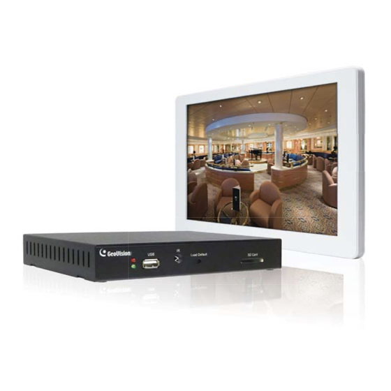
GV-IP Decoder Box and GV-Pad
Note: no SD/SDHC card slot or local storage function in Argentina
Thank you for purchasing GV-IP Decoder Box and GV-Pad. This guide is designed to assist the
new user in getting immediate results from the GV-IP Decoder Box and GV-Pad. For advanced
information on how to use the GV-IP Decoder Box and GV-Pad, please refer to GV-IP Decoder
Box and GV-Pad User's Manual on Software DVD.
© 2011 GeoVision Inc. All rights reserved.
1
Introduction
Welcome to the GV-IP Decoder Box / GV-Pad Quick Start Guide. In the
following sections, you will learn about the basic configuration and features
of the GV-IP Decoder Box / GV-Pad. For a detailed user's manual, see
GV-IP Decoder Box and GV-Pad User's Manual on software DVD.
GV-Video Server
GV-Compact DVR
Analog camera
Packing List
GV-IP Decoder Box
● GV-IP Decoder Box × 1
● AC/DC adapter × 1 (12 V, 3 A, 36 W)
● Software DVD x 1
GV-Pad
● GV-Pad × 1
● Magnetic hinge x 1
● AC/DC adapter × 1 (12 V, 3 A, 36 W)
2011/11
● Software DVD x 1
English
DBV10-QG-A
GV-IP Decoder Box
LAN
or
GV-PT/PTZ
GV-IP Camera
or
GV-Pad
Computer installed
with GV-System and
GV-Mobile Server
GV-IP devices,
analog cameras
Some 3
rd
party
and some
third-party
IP cameras
cameras
through RTSP
● IR remote control × 1
● Power cord x 1
● IR remote control × 1
● Screw x 4
● Power cord x 1
Advertisement
Table of Contents

Related Manuals for GeoVision GV-IP


Summary of Contents for GeoVision GV-IP
- Page 1 ● Magnetic hinge x 1 ● Screw x 4 Thank you for purchasing GV-IP Decoder Box and GV-Pad. This guide is designed to assist the new user in getting immediate results from the GV-IP Decoder Box and GV-Pad. For advanced ●...
-
Page 2: Compatible Devices
Compatible Devices The GV-IP Decoder Box / GV-Pad is compatible with most GeoVision IP To decode and display non-H.264 IP channels or analog channels, connect devices (of the indicated firmware versions) and several third-party IP the devices to GV-System and access them through GV-Mobile Server. The devices that support RTSP. -
Page 3: Gv-Ip Decoder Box
IR remote control. Note: The SPDIF and L/R ports are not functional. Default Reset the GV-IP Decoder Box to the default factory settings. Use a pin to press the button until the green LED fades. This will take about 10 seconds. - Page 4 GV-Pad Right Panel View Left Panel View Name Function Name Function MENU ● Switch to the setup menu. SD Card Slot Connect to an SD card for local storage of ● Load default: Press for 10 seconds to load default snapshot and firmware upgrade.
-
Page 5: The Ir Remote Control
Marks keys Back Back to the previous page in the Setup Menu. Note: The Shift key is only functional for GV-IP Decoder Box. Arrow ● Move up, down, right and left in the Setup Menu. ● Right arrow key: select a channel on the Device List. - Page 6 1. Connect to power using the supplied power adapter. Note: 2. Connect to a standard network cable. 1. The GV-IP Decoder Box can only be connected to one display device through the HD or VGA connector. 3. Turn the Power switch to ON.
- Page 7 OK. This window appears. The GV-IP Decoder Box / GV-Pad contains two sets of ID and password: one set is required when configuring GV-IP Decoder Box through GV-IP Device Utility; the other set is for direct connection between GV IP devices and GV-IP Decoder Box.
- Page 8 Displaying Channels from GV IP Devices B. Type the ID and password and press OK to confirm. The Use the search feature on GV-IP Decoder Box to display channels of GV IP maximum number of characters is 14. devices installed under the same LAN.
-
Page 9: Displaying Channels Using Gv Ip Device Utility
To access the channels connected to GV-System, see 2.6 Displaying Channels from GV-System in GV-IP Decoder Box and GV-Pad User’s 4. Type the ID and password of your GV-IP Decoder Box and click OK. Manual on software DVD. For detail, see step 3 in 4. Configuring the IP Address, ID and... - Page 10 The IP devices under the same LAN with the GV-IP Decoder Box will be A. Click Tool on the Video Connection Setting window, and select Add Camera. This dialog box appears. listed in the Camera List column, and the connected channels will be listed in the Connection Information column.
-
Page 11: Taking A Snapshot
Connection Information list. The channels will be displayed according to this order. 9. Click Save. The cameras on the Connection Information column will be updated to the GV-IP Decoder Box and displayed on the monitor. -
Page 12: Pausing The Looped View
A loop sign with a cross will appear on the top-right corner of the display channel. To resume to the looped view, press 2. Connect the USB drive or SD card to the GV-IP Decoder Box / GV-Pad. key again.
Need help?
Do you have a question about the GV-IP and is the answer not in the manual?
Questions and answers