Advertisement
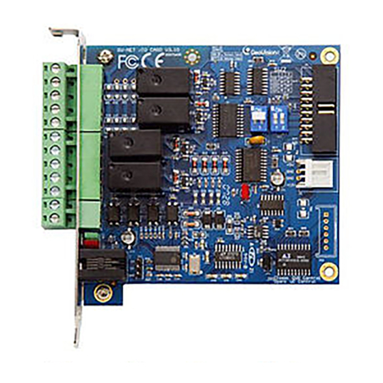
GV-NET/IO Card V3.1
The GV-NET/IO Card is a RS-485 / RS-232 interface converter, and provides 4 inputs and 4
relay outputs as well. It supports both DC and AC output voltages.
Key Features
•
A USB port is provided for PC connection, and it is used with 30 DC output voltages.
•
It can switch between two modes, NET/IO Card Mode and I/O Box Mode, which expand
its capability.
•
Up to 4 GV-NET/IO Cards can be chained together when it is on the I/O Box Mode.
•
It can act as an independent device when it is on the I/O Box Mode.
Packing List
1. GV-NET/IO Card x 1
2. 20-Pin Ribbon Cable with 4 Connectors x1
3. RJ-11 to DB9 Cable x 1
4. RJ-11 to USB Cable x 1
5. 3-Pin Internal USB Cable x 1
6. 4-Pin to 4-Pin Mini Power Cable x 1
7. Installation Guide x 1
May 26, 2011
1
Overview
1
Relay Out 1
GV-NET I/O Card
Relay Out 2
Relay Out 3
Relay Out 4
Com
Input 1
Input 2
Input 3
Input 4
Ground
RS-485 +
RS-485 -
GV Video Capture Card
GV-NET/IO Card connections
Note:
1. The supplied RJ-11 to DB9 Cable of older versions is not compatible with the GV-NET/IO
Card V3.1.
Version 3.1
With a PC Mark
2. When the GV-NET/IO Card V3.1 is in the I/O Box mode, it is incompatible with the GV-IO 12-
In Card of versions earlier than V3.
3. To prevent the noise interference in I/O operation, tightly screw the GV-NET/IO Card V3.1 to
the PC case.
ON
ON
1 O N
1
1
2
ON
4-pin to 4-pin Mini
4
Power Cable
6
20-pin
Ribbon Cable
Older Versions
Without a PC Mark
2
May 26, 2011
Advertisement
Table of Contents

Related Manuals for GeoVision GV-NET/IO Card v3.1


Summary of Contents for GeoVision GV-NET/IO Card v3.1
- Page 1 Without a PC Mark With a PC Mark 2. When the GV-NET/IO Card V3.1 is in the I/O Box mode, it is incompatible with the GV-IO 12- In Card of versions earlier than V3. 3. To prevent the noise interference in I/O operation, tightly screw the GV-NET/IO Card V3.1 to the PC case.
- Page 2 Connections with Two Video Capture Cards 4. Ensure to connect the GV-NET/IO Card to the 20-pin GV-NET/IO port on the GV-Combo A Card as illustrated below. The wrong connection may lead to the GV-NET/IO Card or the GV- If your system is equipped with two video capture cards, connect the GV-NET/IO Card to the Combo A Card to be damaged, causing Video Lost or an error message of “can’t find keypro”...
- Page 3 You can connect a RJ-11 to USB Cable to the PC's USB Port when a RS-485 device is Connections In I/O Box Mode connected. (Allowed for AC/DC Output Voltage) For the connections in the I/O Box Mode, please follow the instructions below: GV Video Capture Card •...
-
Page 4: Switching Modes
NET/IO Card is on the I/O Box mode. For extended connections, the address assignment is shown below. Address Switch Address Assignment Chaining together with GV Video Capture Card GV-NET/IO Card V3.1 / OFF/OFF GV-IO USB Box Address 1 1 O N (white) -
Page 5: Installing Usb Driver
1. Insert the software CD. It will run automatically and pop up a window. Input Input 2. Select Install or Remove GeoVision GV-Series Driver, and then click Install Input Signal Dry Contact, Wet Contact 9~30V AC/DC GeoVision USB Devices Driver. This dialog box appears.
Need help?
Do you have a question about the GV-NET/IO Card v3.1 and is the answer not in the manual?
Questions and answers