
Related Manuals for GeoVision GV-GVS2100


Summary of Contents for GeoVision GV-GVS2100
- Page 1 Quick Start Guide GV-GVS2100 Before attempting to connect or operate this product, TVS-QG-A please read these instructions carefully and save this manual for future use.
- Page 2 GeoVision. Every effort has been made to ensure that the information in this manual is accurate. GeoVision, Inc. makes no expressed or implied warranty of any kind and assumes no responsibility for errors or omissions. No liability is assumed for incidental or consequential damages arising from the use of the information or products contained herein.
- Page 3 Warning and Caution ⚫ If the product does not work properly, please contact your dealer or the nearest service center. Never attempt to disassemble the camera yourself. (We shall not be responsible for any problems caused by unauthorized repair or maintenance.) ⚫...
-
Page 4: Table Of Contents
Contents 1. Overview ......................1 2. Installation ......................2 3. Connection ......................4 4. Accessing the Network Camera ................ 5 4.1 Looking Up the Dynamic IP Address ............5 4.2 Configuring the IP Address ............... 7 5. The Web Interface ....................8 6. -
Page 5: Overview
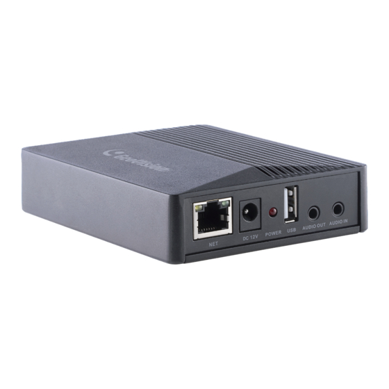
1. Overview Note: The video server can be powered by DC 12 V / PoE power supply. To load default settings, press and hold the default button for 10 seconds. The USB port is currently not functional. -
Page 6: Installation
2. Installation Drill the screw holes on the wall according to the drill template. Insert two screw anchors. - Page 7 Secure the bracket 1 onto the wall with two tapping screws. Install the bracket 2 to the device with two machine screws as shown below. Hook the device to the bracket 1. The device will be locked when a click is heard.
-
Page 8: Connection
3. Connection 12 V Rear panel Power the video server by the following two alternatives: Connect an Ethernet cable to the PoE port. Connect a DC 12 V power adapter to the video server. Note: The USB port is currently not functional. The camera can be optionally powered by the main body by connecting two power wires (+, -) from the camera to the power output ports (12 V, GND) on the main body. -
Page 9: Accessing The Network Camera
4. Accessing the Network Camera Looking Up the Dynamic IP Address By default, when the camera is connected to a LAN with the DHCP server, it is automatically assigned with a dynamic IP address. Follow the steps below to look up its IP address. - Page 10 4. For first-time users, you are requested to create a password. 5. Type a new password and click OK. 6. Click on its IP address again and select Webpage to open its Web interface. 7. Type the set password on the login page and click Login. Note: To change the password using GV-IP Device Utility, click on the camera’s IP address, and select Configure >...
-
Page 11: Configuring The Ip Address
Configuring the IP Address If the camera is connected to a LAN without the DHCP server, the default IP address will be 192.168.0.10. Follow the steps below to modify the IP address to avoid IP conflict with other GV-IP devices on the same LAN. 1. -
Page 12: The Web Interface
5. The Web Interface Once you log in the Web interface, you will see the live view as shown below. The following table is the instructions of the icons on the live view interface. Icon Description Icon Description Original size SD card recording indicator Fit correct scale Sensor alarm indicator... - Page 13 Icon Description Icon Description Alarm output indicator Heat map indicator COC (UTC) control For detailed information, see the user’s manual.
-
Page 14: Upgrading System Firmware
6. Upgrading System Firmware GeoVision periodically releases updated firmware on the company website. To load the new firmware into the camera, follow the instructions below. 1. On the Web interface, click Config > Maintenance > Upgrade. 2. Click the Browse button to locate the firmware file saved at your local computer. -
Page 15: Restoring To Factory Default
7. Restoring to Factory Default If for any reason the camera is not responding correctly, you can restore the camera back to its factory default settings using the Web interface or the Load Default Button. On the device 1. Find the Reset button on the camera (see 1. Overview in the Quick Start Guide). 2.
Need help?
Do you have a question about the GV-GVS2100 and is the answer not in the manual?
Questions and answers