Advertisement
Quick Links
Technical Support Dept. T. 02920 858585 F. 02920 858586
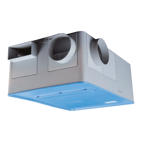
ES-MEV - Hints & Tips
1.0. On Installation
Follow the installation and maintenance document
671266 for ES-MEV, paying particular attention to;
1.1.
a). Mounting the unit using the integral mounting
b). Mount the unit on a non reverberant surface.
c).
d). Make sure that when the unit is mounted
Circuit board connections.
1.3 Setting to work
When initially powered the ES-MEV will self
calibrate, it will try to achieve the duties set by
the MAX and MIN set points.
The calibration process can take around 2 minutes
and is as follows:
■
Unit runs to full speed. (Faster than the max
set point).
■
The unit will slow down and eventually stop.
■
A 10 second wait.
■
It will restart and run at ¼ speed.
■
The unit then settles to the MIN speed.
If, during this process the red LED should illuminate,
ensure there are no switched live or boost signals
present.
Upon completion of the calibration process apply a
switched live (SL), the fan speed and duty should
increase to that of the MAX set point.
When testing a system
a). The 'dial a duty' set points should be positioned
0.01
b). On an existing installation it is important to
Nuaire Group Western Industrial Estate Caerphilly United Kingdom CF83 1NA
Telephone: 029 2085 8200 Facsimile: 029 2088 7033 Email: info@nuaire.co.uk www.nuaire.co.uk
The chosen location for installation.
bracket supplied.
The unit can be mounted at any angle.
sufficient space is left around the unit for
maintenance and the fixing of the ducting.
N
L
SL
230V Switched live
with the MAX at MAX and MIN at MIN, i.e.
giving the widest possible speed control range.
observe and note these duty positions should
it be necessary to return to them later.
GUIDANCE NOTES 10
e).
If installed with flexible duct special care/
consideration should be made to prevent the
duct being closed off, cracked or twisted,
introducing a high resistance on the system.
1.2. Electrical.
a). Pay particular attention to electrical
connections referring to the I&M for correct
method.
b). Isolation of the unit and any switched live
circuits should be achieved through the same
isolator.
Do not use
To remote
fail indicator
ES-MEV-AVI
c). The SL run on should be set to minimum to
reduce the run on time during test, it is
important to note the position set should it be
necessary to return to it later.
TEST BUTTON
SL RUN ON
MAX SPEED
ADJUST
MIN SPEED
ADJUST
LED
1
Internal
To OPUS-SPD
speed control
humidity adj.
Calibration
60
Run-on
30
(mins)
0
90
Max
50
Airflow
(l/s)
10
90
Min
50
Airflow
(l/s)
10
Status
Calibration
Run-on
30
(mins)
Max
50
Airflow
(l/s)
Min
50
Airflow
(l/s)
Status
continued overleaf.
Leaflet Number 671414 January 2010
60
0
90
10
90
10
Advertisement

Subscribe to Our Youtube Channel
Related Manuals for NuAire ES-MEV


Summary of Contents for NuAire ES-MEV
- Page 1 Nuaire Group Western Industrial Estate Caerphilly United Kingdom CF83 1NA Telephone: 029 2085 8200 Facsimile: 029 2088 7033 Email: info@nuaire.co.uk www.nuaire.co.uk Leaflet Number 671414 January 2010...
- Page 2 GUIDANCE NOTES 10 - Hints & Tips ES-MEV 2.0 On Maintenance is correct and no boost signal is present. If a fault still exists, in the first instance please call our 2.1 Motors contain sealed for life bearings, no technical department on 029 2085 8585.
- Page 3 GUIDANCE NOTES 10 - Hints & Tips ES-MEV 5.0 ES-MEV Replacement of Remove the 2 ‘mate-n-lock’ plugs that inter connect the PCB’s. the 830178 PCB Undo the central mounting screw and lift the PCB. 5.1 The replacement of the PCB should be under...
Need help?
Do you have a question about the ES-MEV and is the answer not in the manual?
Questions and answers