Table of Contents
Advertisement
Quick Links
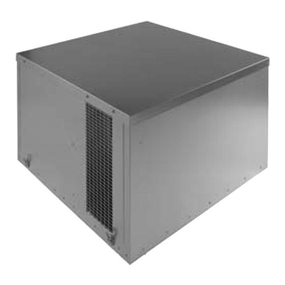
EST-X
Removable top panel
C
Commissioning
box
A
Figure 1. EST*-X Plantroom/roof mounted in line unit.
Table 1. Dimensions (mm)
Unit
A
EST 19H-X
1430
EST 20H-X
2030
EST-R
A
Removable
top panel
C
Opposed outlet grilles
External
commissioning box.
Figure 2. EST*-R Roof mounted end inlet, side discharge unit.
Table 2. Dimensions (mm)
Unit
EST 19H-R
1430
Introduction
The Nuaire EST Twinfan Belt Drive range consists of the
following units
EST-X (Duct Mounted, Plantroom/Roof) in line unit.
EST-R (Roof Mounted, end inlet) side discharge unit*.
EST-B (Roof Mounted bottom inlet) side discharge unit*.
Units are rectangular in section. The casing is manufactured
from heavy gauge 'Aluzinc' aluminium-zinc coated mild steel.
A full size internally lined access panel is fitted to the top face
and this panel is fully detachable for inspection purposes.
The motor plate and frames are supported on the base by
resilient mountings allowing the fan unit to be operated without
the need for separate anti vibration fan case mountings.
Nuaire: A Trading Division of Polypipe Limited Western Industrial Estate Caerphilly United Kingdom CF83 1NA
T: 029 2088 5911 F: 029 2088 7033 E: info@nuaire.co.uk W: www.nuaire.co.uk
EST 19H & 20H
3ph Run & Standby, Roof &
Plantroom Twinfans
E
50mm
D dia
F
Circular spigots
size EST19H)
B
Rectangular spigots
size EST20H)
For unit weights see page 4
B
C
D dia
E
840
1635
630
-
2313
1183
-
1200
B
D dia
Control module
located internally
For unit weights see page 4
A
B
C
D dia
840
1635
630
Suitable for operation in ambient temperatures up to 40
Handling
Always handle the units carefully to avoid damage and distortion.
Eyebolts are provided on all units for lifting purposes.
If mechanical aids are used to lift the unit, spreaders should be
employed and positioned so as to prevent the slings, webbing
etc. making contact with the casing.
EST-B
F
-
700
C
Opposed outlet grilles
Figure 3. Bottom inlet unit.
Table 3. Dimensions (mm)
Unit
EST 19H-B
EST-B/R larger units
Commissioning box
C
F
Figure 4. Bottom inlet unit.
Table 4. Dimensions (mm)
Unit
EST 20H-B
EST 20H-R
1
The EMC Directive
2014/30/EU
The Low Voltage
Directive
2014/35/EU
Commissioning box
B
A
Removable
top panel
Bottom inlet
Control module
F
E
located internally
For unit weights see page 4
A
B
C
840
1430
1635
889
* larger units have end discharge
End inlet rectangular spigot Code: EST*-R
B
A
E
Bottom rectangular inlet
F
E
spigot Code: EST*-B
For unit weights see page 4
A
B
C
2030
2313
1183
1200
2030
2313
1183
1200
28. 06. 17. Leaflet Number 671845
o
C.
Rect Spigot
E
F
381
Louvred
end outlet
Rect Spigot
E
F
700
700
Advertisement
Table of Contents

Subscribe to Our Youtube Channel
Related Manuals for NuAire EST 19H-R


Summary of Contents for NuAire EST 19H-R
- Page 1 Nuaire: A Trading Division of Polypipe Limited Western Industrial Estate Caerphilly United Kingdom CF83 1NA T: 029 2088 5911 F: 029 2088 7033 E: info@nuaire.co.uk W: www.nuaire.co.uk...
- Page 2 Installation and Maintenance ECOSMART EST 19H & 20H Roof & Plantroom Twinfans Installation Testing after installation IMPORTANT Ensure that the Fan unit and any specified controls are fitted The installation must be carried out by competent personnel securely according to the instructions. in accordance with the appropriate authority and conforming Switch on the mains supply.
- Page 3 Electrical Installation typical layout Figure 8. EST19H typical internal layout. Isolation - Before commencing work make sure that the unit, switched live and Nuaire control are electrically isolated from the mains supply. Warning - Inverter Speed Control An Inverter is used to provide speed control. When the fan is isolated, allow 5 minutes for the capacitors in the inverter to discharge before commencing any work on the unit.
- Page 4 Installation and Maintenance ECOSMART EST 19H & 20H Roof & Plantroom Twinfans Connections Note that the volt free contacts are not fused. If these are used to power any external equipment, the installer must provide a) Mains connections adequate fusing or other protections. Mains cables should be suitably sized and terminated at These contacts are rated at 5A resistive, 0.5A inductive.
- Page 5 Installation and Maintenance ECOSMART EST 19H & 20H Roof & Plantroom Twinfans Figure 15. The Control Module Three Phase No user Connection Remove this link wire if a switched live signal is connected to terminal SL Note: also remove link if a BMS system is connected.
- Page 6 Isolation - Before commencing work make sure mounting furthest from the fan and slacken the remaining two that the unit, switched live and Nuaire control are bolts. Lift the motor plate and remove the belt. Replacing the belt electrically isolated from the mains supply.
-
Page 7: Operation And Maintenance
The equipment referred to in this Declaration of Incorporation is supplied by live are not prevented by the equipment panels or by fixed installation detail Nuaire to be assembled into a ventilation system which may or may not include (eg ducting), then guarding to the appropriate standard must be fitted.
Need help?
Do you have a question about the EST 19H-R and is the answer not in the manual?
Questions and answers