Table of Contents
Advertisement
Quick Links
QUICK START
Make all connections with the power and amplifiers off. The SRM 66 is fully balanced and equipped with removable
5-wire Euroblock connectors. Inputs and Outputs are arranged on Euroblocks in pairs, i.e. 1&2, 3&4, 5&6.
Be sure the FP LOCK switch is in the out position to enable programming from the front panel.
Apply power so the PWR light and LCD screen glows with the SRM 66 welcome marquee. During initialization, The
startup muting circuit immediately starts counting down from 40 in the Limiter Gain Reduction area of the display. Adjust
the VIEWING ANGLE with a miniature screwdriver if necessary.
With signal applied to the Inputs, watch the MIX INPUT HEADROOM indicators. These verify correct setting of the
Output of the previous device and the rear panel GAIN switches. Adjust so that 4 dB lights during peaks.
Navigating the Edit pages is simple. The top buttons marked << and >> are the left/right Page scroll buttons. These
navigate to the Channel pages 1 through 6, the Assign Channel to Group page, the Assign Remote to Group page, the
Group levels page, and the Memory page.
The bottom buttons marked < and > are the left/right cursor buttons. These select the (underlined) parameter to edit.
Rotating the DATA knob changes the parameter setting.
Let's start by navigating to Channel 1's page. Move the cursor to IN1. With a signal driving Input 1 and a working
amplifier connected to Output 1, adjust the DATA knob to the desired level. Adjust any other Input going to Channel
Output 1. MST controls the Master Output level of Channel 1. LMT sets the Limit Threshold of the Limiter circuit. for
Channel 1.
To Copy settings from Channel 1 to any other Channel, move the cursor to COPY. Press the EXE button. The display
now reads PASTE. Change the page to the one you want these same settings in, and press EXE again. The settings have
now been pasted into the new Channel.
Settings may be Stored and Recalled in the Memory Page. To Store, select the Store field, select a Memory number
with the DATA wheel and press EXE. To Recall, select the Recall field, select a Memory number with the DATA wheel
and press EXE. Look deeper into this manual for remote control of Memories and level adjustments.
CAUTION: Never connect anything except an approved Rane Power supply to the thing that looks like a red tele-
phone jack on the rear of the SRM 66. This is an 18 VAC center tapped power input. Consult the Rane factory for a
replacement or substitution.
SRM 66 CONNECTION
Balanced Operation
Connect the '+' to '+', '–' to '–', and shield to shield. Use
only when driving from a true balanced source and driving to
a true balanced destination—either transformer coupled or
active drive.
Unbalanced Operation
To avoid nasty side effects such as hum and noise, this is
to be avoided—but when you must, keep cable lengths as
short as possible. For lengths longer than ten feet, use a
transformer or a Rane BB 44x.
Coming from an unbalanced source into the SRM 66
using two conductors with shield, connect '+' to '+', the
OPERATORS MANUAL
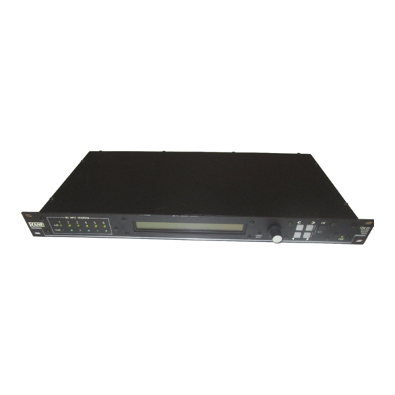
SPLITTER ROUTER MIXER
unbalanced source ground to '–', and the cable shield to the
SRM 66 ground.
Going to an unbalanced device using a single conductor
with shield, connect '+' to '+', leave '–' unconnected and
connect the cable shields at both ends to ground.
Combination Operation
For combined balanced and unbalanced operation, use
whichever half of the above instructions apply for each end.
See the "Sound System Interconnection" RaneNote
included with this manual for more information on cabling
and grounding requirements.
www.audiovias.com
SRM 66
Manual-1
Advertisement
Table of Contents

Related Manuals for Rane SRM 66


Summary of Contents for Rane SRM 66
- Page 1 CAUTION: Never connect anything except an approved Rane Power supply to the thing that looks like a red tele- phone jack on the rear of the SRM 66. This is an 18 VAC center tapped power input. Consult the Rane factory for a replacement or substitution.
- Page 2 INTERNAL 80 Hz HIGHPASS FILTERS Each Output of the SRM 66 features an internally switchable 80 Hz highpass filter. These filters roll off low frequen- cies, valuable in small sound reinforcement systems and for use with constant voltage line transformers. These are shipped from the factory in the OUT position.
- Page 3 REAR PANEL DESCRIPTION 1. POWER input connector. Use only an RS 1, or other remote AC power supply approved by Rane. This unit is supplied with a remote power supply suitable for connection to this input jack. Consult the factory for replacement or substitution.
- Page 4 [y]dB when indicates -59 dB and Off. for Output All programming of the SRM 66 is done with the Data the Limiter is active. the Output [x]. Range wheel and the buttons on the front panel using one of the ten...
- Page 5 Figure 5. Double-check all wiring for accuracy before power is Each of the 12 Memories stored in the SRM 66 may have applied to the SRM 66. A single LED should light immedi- unique Group assignments for Outputs and SR 1 Remotes.
- Page 6 Figure 6 on the previous page. Memory Recall Port In addition to the Memory page, the SRM 66 provides a Memory Recall Port (MRP). This Port allows remote switch closures to recall any of the twelve system Memories.
- Page 7 Group. Control Control Group 2 Group 1 Conference Room Memory 2 Remote 2 Remote 1 Figure 10. Room Combining System www.audiovias.com ©Rane Corporation 10802 47th Ave. W., Mukilteo WA 98275-5098 TEL (425)355-6000 FAX (425)347-7757 WEB http://www.rane.com Manual-7...
Need help?
Do you have a question about the SRM 66 and is the answer not in the manual?
Questions and answers