Table of Contents
Advertisement
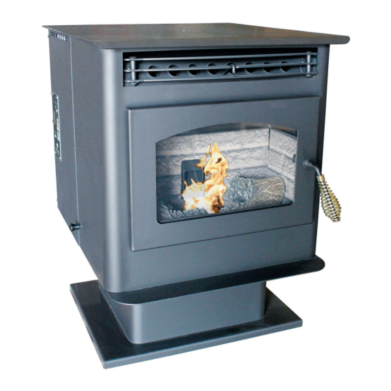
Owner's Instruction and Operation Manual
Model Number:
5040
Report Number: F21-687
Certified to ASTM E1509-12 (2017),
ULC-S627-00-REV1
* All Pictures In This Manual Are For Illustrative Purposes Only. Actual Product May Vary.
Save These Instructions In A Safe Place For Future Reference.
SAFETY NOTICE: If this heater is not properly installed, a house fire may result. For
your safety, follow the installation instructions. Never use make-shift compromises
during the installation of this heater. Contact local building or fire officials about
permits, restrictions and installation requirements in your area. NEVER OPERATE
THIS PRODUCT WHILE UNATTENDED.
CAUTION! Please read this entire manual before you install or use your new room
heater. Failure to follow instructions may result in property damage, bodily injury, or
even death. Improper Installation Will Void Your Warranty!
U.S. Environmental Protection Agency
Certified to comply with 2020 particulate
emissions standards.
THIS MANUAL IS SUBJECT TO CHANGE WITHOUT NOTICE.
© 2021 United States Stove Company, 227 Industrial Park Rd., South Pittsburg, TN 37380
Golden
Eagle
R
CALIFORNIA PROPOSITION 65 WARNING:
This product can expose you to chemicals including carbon
monoxide, which is known to the State of California to cause
cancer, birth defects, and/or other reproductive harm. For
more information, go to www.P65warnings.ca.gov
8 5 2 0 1 0 J -1 3 0 3 K
Ph. 800-750-2723
Advertisement
Table of Contents

Related Manuals for Golden Eagle 5040


Summary of Contents for Golden Eagle 5040
- Page 1 Owner’s Instruction and Operation Manual Golden Eagle Model Number: 5040 Report Number: F21-687 Certified to ASTM E1509-12 (2017), ULC-S627-00-REV1 * All Pictures In This Manual Are For Illustrative Purposes Only. Actual Product May Vary. 8 5 2 0 1 0 J -1 3 0 3 K Save These Instructions In A Safe Place For Future Reference.
- Page 2 INTRODUCTION This manual describes the installation and operation of the Golden Eagle, 5040 wood heater. This heater meets the 2020 U.S. Environmental Protection Agency’s crib wood emission limits for wood heaters sold after May 15, 2020. Under specific test conditions this heater has been shown to deliver heat at rates ranging from 4,814 to 32,788 Btu/ hr, 0.49 g/hr, and 63% efficiency.
-
Page 3: Installation Checklist
INSTALLATION CHECKLIST Your Wood Stove should be installed by a qualified installer only. An NFI qualified Installer can be found at www. nficertified.org/public/find-an-nfi-pro/ CUSTOMER SERVICE 1-800-750-2723 ext 5050 Text to 423-301-5624 Email to: Customerservice@usstove.com COMMISSIONING CHECKLIST This checklist is to be completed in full by the qualified person who installs this unit. Keep this page for future reference. Failure to install and commission according to the manufacturer’s instructions and complete this checklist will invalidate the warranty. -
Page 4: Installation
INSTALLATION CAUTION: SAFETY NOTICE BURNING FUEL CREATES CARBON MONOXIDE • IF THIS STOVE IS NOT PROPERLY INSTALLED, AND CAN BE HAZARDOUS TO YOUR HEALTH IF A HOUSE FIRE MAY RESULT. TO REDUCE THE NOT PROPERLY VENTED. RISK OF FIRE, FOLLOW THE INSTALLATION INSTRUCTIONS. -
Page 5: Alcove Clearances
INSTALLATION PREPARATION WITH 1” 3” VERTICAL Factory packaging must be removed, and some minor 3” 1” EXHAUST assembly work is required prior to installation. Access 3” to the rear of the stove is necessary. The circuit board/ 8 1/4” control panel must be unpacked and installed in the side (TOP) flashing on the insert or side panel on the freestanding. -
Page 6: Importance Of Proper Draft
21 1/2” INSTALLATION 5 7/8” INLET IMPORTANCE OF PROPER DRAFT flexible or rigid, may be attached to the inlet at the stove’s EXHAUST 28 1/2” PIPE PIPE rear. A rodent guard (minimum 1/4” wire mesh)/wind Draft is the force which moves air from the appliance hood must be used at the terminus. -
Page 7: Horizontally Through Wall
INSTALLATION bolts provided in the kit into the four holes under the stove 7. Termination should not be located so that hot at each corner, thread on nuts from the top and tighten. exhaust gases can ignite trees, shrubs, or grasses Make sure to save the hole plugs. -
Page 8: Vertically Into Existing Chimney System
INSTALLATION under roofing materials, nail to the roof along upper 2. You will need a pipe length equal to the chimney edge. Do not nail lower edge. Seal nail heads with height from the hearth. If outside combustion air is non-hardening waterproof mastic. -
Page 9: Electrical Installation
INSTALLATION and while holding the pipe at the proper elevation, For installation in a mobile home, an outside source affix the collar with a minimum of three 1/4” stainless of combustion air must be used (see “COMBUSTION steel sheet metal screws. Seal all joints and seams AIR SUPPLY”). -
Page 10: Operation
OPERATION NEVER OPERATE THIS PRODUCT WHILE UNATTENDED PANEL CONTROLS FUEL FEED SWITCH • When the “Fuel Feed” button is pushed and held down the stove will feed pellets continuously into the burnpot. • While the stove’s auger system is feeding pellets the amber light (in the “Fuel Feed”... - Page 11 OPERATION HEAT LEVEL ADVANCE THERMOSTAT INSTALLATION • This button when pushed will set the pellet feed rate, • A MILLIVOLT THERMOSTAT IS REQUIRED. hence the heat output of your stove. The levels of heat • Unplug stove from power outlet. output will incrementally change on the bar graph •...
-
Page 12: Proper Fuel
OPERATION standard (minimum of 40 lbs density per cubic ft, 1/4” to WARNING: 5/16” diameter, length no greater than 1.5”, not less than • DO NOT USE CHEMICALS OR FLUIDS TO START 8,200 BTU/lb, moisture under 8% by weight, ash under THE FIRE - NEVER USE GASOLINE, GASOLINE- 1% by weight, and salt under 300 parts per million). -
Page 13: Damper Control
OPERATION PRE-START-UP CHECK slightly. A “blow torch” fire can be improved by pushing the damper in a bit. As a general rule, on lower feed rate Remove burn pot, making sure it is clean and none of the settings, the damper should be in farther. On higher feed air holes are plugged. - Page 14 OPERATION REFUELLING Turning your stove off is a matter of pressing the “Power” control panel switch. The red light will go out. The blowers will continue to operate until internal firebox CAUTION: temperatures have fallen to a preset level. • THE HOPPER AND STOVE TOP WILL BE HOT DURING OPERATION;...
-
Page 15: Maintenance
OPERATION FIGURE 26 CAUTION: • DO NOT OPERATE YOUR STOVE IF YOU SMELL SMOKE COMING FROM IT. TURN IT OFF, MONITOR IT, AND CALL YOUR DEALER. • DO NOT OPERATE THE STOVE IF THE FLAME BECOMES DARK AND SOOTY OR IF THE BURNPOT OVERFILLS WITH PELLETS. - Page 16 up has occurred. If creosote has accumulated, it should be removed to reduce the risk of a chimney fire. Inspect the system at the stove connection and at the chimney top. Cooler surfaces tend to build creosote deposits FIGURE 25 quicker, so it is important to check the chimney from the top as well as from the bottom.
-
Page 17: Spring Shutdown
CHECK & CLEAN THE HOPPER SPRING SHUTDOWN Check the hopper periodically to determine if there is any After the last burn in the spring, remove any remaining sawdust (fines) that is building up in the feed system or pellets from the hopper and the auger feed system. Scoop pellets that are sticking to the hopper surface. -
Page 18: Troubleshooting Guide
TROUBLESHOOTING GUIDE When your stove acts out of the ordinary, the first reaction is to call for help. This guide may save time and money by enabling you to solve simple problems yourself. Problems encountered are often the result of only five factors: 1) poor fuel;... - Page 19 TROUBLESHOOTING GUIDE STOVE SHUTS OFF AND THE #3 LIGHT FLASHES Possible Causes: Possible Remedies: (Unplug stove first when possible) The hopper is out of pellets. Refill the hopper The air damper is too far open for a low If burning on the low setting, you may need to close the damper all the feed setting.
- Page 20 TROUBLESHOOTING GUIDE STOVE FEEDS PELLETS, BUT WILL NOT IGNITE Possible Causes: Possible Remedies: Push the air damper in closer to the side of the stove for start-up. In some situations, it may be necessary to have the damper completely Air damper open too far for ignition. closed for ignition to take place.
- Page 21 TROUBLESHOOTING GUIDE STOVE WILL NOT FEED PELLETS, BUT FUEL FEED LIGHT COMES ON AS DESIGNED Possible Causes: Possible Remedies: Remove the control board. On the back, there is one fuse. If it appears to Fuse on control board blew. be bad, replace it with a 5 Amp 125 Volt fuse. Plug the stove back in and try to run the unit.
- Page 22 TROUBLESHOOTING GUIDE GLASS “SOOTS” UP AT A VERY FAST RATE FLAME IS LAZY, DARK AND HAS BLACK TIPS AFTER STOVE HAS BEEN ON FOR A WHILE, THE BURNPOT OVERFILLS Possible Cause: Possible Remedies: Stove or vent pipe is dirty, which restricts Follow all cleaning procedure in the maintenance section of the owner’s airflow through the burnpot.
-
Page 23: Smoke Smell Or Soot Build-Up
TROUBLESHOOTING GUIDE HIGH LIMIT SWITCH KEEPS TRIPPING Possible Causes: Possible Remedies: The convection blower is overheating and Clean any dust off the windings and fan blades. If oiling the blower does tripping the internal temperature shut-off. not help, the blower may be bad The highest level setting is designated for use over short periods of time. -
Page 24: Electrical Diagram
ELECTRICAL DIAGRAM MOLEX CONNECTOR ONG GRY PNK BLU YEL ONG GRY BRN BRN WHT BLK BROWN MOLEX CONNECTOR DETAIL BROWN POF THERMODISC GROUND AIR SWITCH HOPPER HIGH TEMP. IGNITOR SWITCH THERMODISC PURPLE AUGER MOTOR WHITE COMBUSTION CONVECTION BLOWER BLOWER POWER OUTLET DETAIL LOOKING FROM THE REAR WHITE WHITE... -
Page 25: Replacement Parts
REPLACEMENT PARTS © 2021 United States Stove Company... - Page 26 REPLACEMENT PARTS 80461 Power Supply Cord Part # Description 88202 Igniter Housing Gasket 610054 Top Plate Assembly 610058 Pedestal Assembly 88217 Top Insulation 25589 Poker, Burnpot 27777 Exhaust Diverter 69964 Weldment, Burnpot Housing 891121 Pressure Switch Tubing 69965 Weldment, Burnpot 27033 PSS FS Side Sheet Left 27035...
-
Page 27: Service Record
SERVICE RECORD It is recommended that your heating system is serviced regularly and that the appropriate Service Interval Record is completed. SERVICE PROVIDER Before completing the appropriate Service Record below, please ensure you have carried out the service as described in the manufacturer’s instructions. - Page 28 NOTES © 2021 United States Stove Company...
- Page 29 NOTES © 2021 United States Stove Company...