
Related Manuals for Clarke PLS360


Summary of Contents for Clarke PLS360
- Page 1 PETROL POWER WASHER MODEL NO: PLS360 PART NO: 7330375 OPERATION & MAINTENANCE INSTRUCTIONS ORIGINAL INSTRUCTIONS DL 0121 REV 1...
- Page 2 This guarantee does not effect your statutory rights. UNPACKING Unpack your power washer and check to ensure the following items are present. Contact your CLARKE dealer immediately if any parts are missing or damaged. 1 x Petrol Power Washer 1 x Hose/Lance Storage Bracket...
-
Page 3: General Safety Rules
3. DO NOT let children or untrained personnel use this machine. 4. DO NOT operate the machine with any of the covers removed. 5. DO NOT try to repair this machine. Always refer to your CLARKE service department for all repairs. -
Page 4: Safety Symbols
SAFETY SYMBOLS ALWAYS: Read this manual and make sure that all warnings and instructions are clear before you use this pressure washer. DANGER: Risk of fire or explosion. Stop the engine before you refuel the pressure washer. Keep flammable materials away from the work area. -
Page 5: Specifications
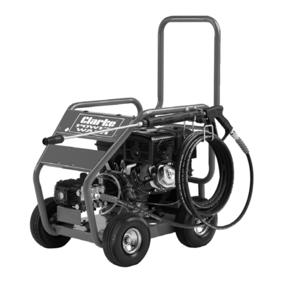
SPECIFICATIONS Model PLS360 Engine Engine Model G390FD Power (HP) 13hp/8.2kW/3600rpm Engine type Petrol (unleaded) Starting system Battery 12V, 20AH Fuel Tank Capacity (L) Water supply Max. feed temperature Min. feed volume (l/min.) Water Inlet Pressure 3-6 Bar Water Pump Maximum pressure... - Page 6 OVERVIEW Parts & Service: 020 8988 7400 / E-mail: Parts@clarkeinternational.com or Service@clarkeinternational.com...
- Page 7 OVERVIEW NO DESCRIPTION NO DESCRIPTION Foldable Handle 10 Pressure Regulator 11 Chemical Detergent Inlet Wand/Lance & Hose Bracket 12 Water Outlet Wheels 13 Water Inlet Engine 14 Suction Valve Pump 15 Thermal Relief Valve Adjustable Nozzle 16 10m High Pressure Hose Spray Wand/Lance 17 Water Inlet Hose with Filter Petrol Tank...
-
Page 8: Fitting The Wheels
ASSEMBLY FITTING THE WHEELS 1. Insert the axle as shown. • Rotate the axle so that the spring loaded pin pops through the hole on the frame. 2. Fit the wheels to the axles and secure with the locking nuts supplied. - Page 9 THE HIGH PRESSURE HOSE CONNECT THE HOSE TO THE GUN 1. Slide the connector on the hose backwards. 2. Push the gun into the connector. 3. Release the connector. NOTE: Make sure the connection is secure. CONNECT THE HOSE TO THE POWER WASHER 1.
-
Page 10: Connecting The Battery
LANCE & HOSE STORAGE BRACKET 1. Fit the bracket into the position shown and secure using the washers and nuts supplied. REMOVE THE TRAVEL PLUGS BEFORE USE. 1. Use a 17mm spanner to remove the red travel plugs. 2. Inside the small bag attached are oil breather plugs which need to be fitted in its place. -
Page 11: Before Use
BEFORE USE WARNING: TO CARRY OUT THIS CHECK, PLACE THE POWER WASHER ON LEVEL GROUND WITH THE ENGINE SWITCHED OFF. IMPORTANT: The engine is supplied without any oil in it and must be filled to the correct level before use, see below. NOTE: All oil levels should be checked when the engine is cold, as you may get a false reading with a hot engine. -
Page 12: Checking The Engine Oil Level
CHECKING THE ENGINE OIL LEVEL WARNING: RUNNING THE ENGINE WITH INSUFFICIENT OIL WILL CAUSE ENGINE DAMAGE. 1. Turn the oil filler cap/dipstick anti- clockwise and remove it from the oil filler tube. 2. Wipe the oil filler cap/dipstick with a clean cloth. 3. -
Page 13: Pressure Regulator
3. Refuel in a well-ventilated area before starting the engine. If the engine has been running, allow it to cool. Refuel carefully to avoid spilling fuel. Do not fill above the fuel strainer shoulder. 4. After refueling, replace the fuel filler cap securely. - Page 14 STARTING YOUR POWER WASHER WARNING: FAILURE TO TURN ON THE WATER COULD CAUSE DAMAGE TO THE PUMP. Prior to starting, refer to your engine manual for proper starting procedures for your engine type. 1. Make sure the engine has sufficient fuel. See page 12. 2.
- Page 15 7. If you are starting the power washer ‘cold’ set the choke lever to the CHOKE position (left). If the power washer is warm then set the lever to the ‘RUN’ position. 8. Turn the ignition key to the ‘ON’ position, then turn the key to the ‘START’...
- Page 16 USING THE POWER WASHER 1. Pull the trigger on the gun to start water flow. • Stand on a stable surface and grip the gun/spray wand firmly with both hands. • Expect the gun to kick when the trigger is pulled. 2.
-
Page 17: Adjusting The Pressure
• Slide the nozzle forward for low pressure and backwards for high pressure. ADJUSTING THE PRESSURE There are 4 ways to adjust the pressure. 1. Adjust the pressure regulator on the pump. Turn the pressure regulator knob counter clockwise to lower pressure. Once you have finished using your power washer, return the pressure regulator to its original position. -
Page 18: Shutting Down
3. Slide the nozzle forward for low pressure operation. NOTE: See page 30 for detergent and cleaning products available from your CLARKE dealer. SHUTTING DOWN 1. After each use, if you have applied detergents, place the detergent hose into a container of clean water and run clean water through the detergent injection system to flush the system thoroughly. - Page 19 WATER BUTT CONNECTION This machine has the ability to draw its own water, meaning you can use water not under pressure, such as rainwater collected in a water butt. To do this you must carry out the following procedure. 1. Attach the filter to the end of the pipe supplied.
-
Page 20: Maintenance
NOTE: DO NOT let the pressure washer run dry. MAINTENANCE CHANGING THE PUMP OIL CAUTION: PROLONGED EXPOSURE TO USED OIL IS DANGEROUS, ALWAYS WASH YOUR HANDS THOROUGHLY AFTER HANDLING USED OIL. 1. Unscrew and remove the oil filler cap. 2. Place an oil collection tray (not supplied) under the drain plug. -
Page 21: Cleaning The Nozzle
CLEANING THE NOZZLE If the nozzle becomes partially clogged or restricted by dirt or other foreign material, excess pump pressure may develop. Clean the nozzle immediately by following the instructions below. 1. Shut off the power washer and turn off the water supply. 2. -
Page 22: Checking The Air Filter
3. Make sure that the air filter is clean and not damaged. • If the air filter is damaged contact CLARKE spare parts department for a replacement. • If the filter is dirty, wash it in a solution of warm water and mild detergent and rinse thoroughly. -
Page 23: Storage Procedure
STORAGE ENGINE See the separate engine manual supplied, for information regarding the stor- age procedure. PUMP 1. Drain all water from the high pressure hose, coil it and store it on the hose holder, located on the rear of the power washer. 2. -
Page 24: Troubleshooting
TROUBLESHOOTING If the following does not solve your problem, please contact the CLARKE service department. PROBLEM CAUSE SOLUTION Engine will not No fuel Add fuel (See Page 12) start, see Low oil Add oil (See Page 11-12) engine manual for further... - Page 25 PROBLEM CAUSE SOLUTION Lack of Water supply is not Make sure your water supply can pressure (initial adequate deliver 25 litres per minute at 20psi use) Leak in the high Tighten the fitting, use sealant tape if pressure hose fitting required Nozzle is obstructed Clear the nozzle (See Page 20)
- Page 26 PROBLEM CAUSE SOLUTION Water leaking Loose connections Tighten at the pump Piston packings worn Have it replaced by your dealer Worn or broken O-ring Have it replaced by your dealer Pump head or tubes Have it replaced by your dealer. damaged from freezing Oil leaking at...
- Page 27 EXPLODED DIAGRAM - PUMP PARTS LIST- PUMP Bolt, (Crankcase Cover) M6 x16 14 Ball Bearing Oil Drain Plug 15 Scrap Ring O-Ring, Oil Drain Plug 14.2 x 1.9 16 O-Ring, (Crankshaft Cover) 55.25 x 2.62 Vented Oil Cap 17 Retain Ring Crankcase Cover 18 Oil Level Plate Gasket, (Crankcase Cover),...
- Page 28 27 Oil Seal, Plunger 52 Valve Seat 28 Location Ring 53 O-Ring, (Valve Seat )9.25 x 1.78 29 O-Ring, (Locating Ring) 26.7 x 54 Gasket, (Unloader Valve 1.78 Housing) 18 x 2.4 30 Low Pressure Water Seal 55 Detergent Injector Fitting 31 Compression Ring 56 O-Ring, Injector Fitting 4.47 x 1.78...
- Page 29 EXPLODED DIAGRAM - GEARBOX PARTS LIST- GEARBOX Gearbox Case 12 Blocking Flake Oil Plug 13 Bolt M8 x 30 O Ring 14.2 x 1.9 14 Combine Washer Gasket, Oil Gauge 15 O Ring 55.25 x 2.62 Sight Gauge 16 Gearbox Cover Oil Seal 17 Gasket Cover Ball Bearing 61908...
- Page 30 EXPLODED DIAGRAM - FRAME PARTS LIST- FRAME Pump 16 Engine Bolt 17 Handle Pressure Gauge 18 Handwheel Bolt 19 Plain Washer Anti Vibration Holder 20 Hose & Lance Storage Bracket Plain Washer 21 Screw Nut Spring Washer 22 Plain Washer Bolt 23 Frame Body Rubber Feet (Pump)
-
Page 31: Declaration Of Conformity
31 Plain Washer 35 Lance 32 Grommet 36 Gun 33 Frame Faceplate 37 High Pressure Hose 34 Key Start DECLARATION OF CONFORMITY Parts & Service: 020 8988 7400 / E-mail: Parts@clarkeinternational.com or Service@clarkeinternational.com...
Need help?
Do you have a question about the PLS360 and is the answer not in the manual?
Questions and answers