Table of Contents
Advertisement
Quick Links
This manual must be read in its entirety before installation of this burner.
Installation must be performed by a qualified technician and must adhere
to the standards set by the local regulatory authorities.
www.clearrushco.com
www.clearrushco.com
1-877-638-5234
1-877-638-5234
ACL HIGH EFFICIENCY BURNER ASSEMBLY
Installation Manual
Installation Manual
for the
for the
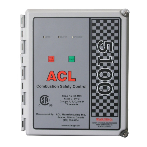
ACL 5100
ACL 5100
Combustion Safety
Combustion Safety
Controller
Controller
WARNING
ACL is not responsible for the misuse or
incorrect application of this product.
(403) 638-5234
(403) 638-5234
Clear Rush Co.
Box 1898, 5406 Township Road 325B
Sundre, AB
T0M 1X0
Canada
Advertisement
Table of Contents

Related Manuals for ACL ACL 5100


Summary of Contents for ACL ACL 5100
- Page 1 This manual must be read in its entirety before installation of this burner. Installation must be performed by a qualified technician and must adhere to the standards set by the local regulatory authorities. ACL is not responsible for the misuse or incorrect application of this product. Clear Rush Co.
- Page 2 ACL 5100 Combustion Safety Controller ACL 5100 Combustion Safety Controller...
- Page 3 ACL 5100 Combustion Safety Controller ACL 5100 Combustion Safety Controller ACL 5100 Provides ACL 5100 Provides SINGLE & THREE TRIALS FOR IGNITION FLAME MONITORING INDICATION OF PILOT ON & SYSTEM ON ALARM INDICATION OF FLAME FAIL, POWER FAIL, & SHUTDOWN...
- Page 4 Once the gas is lit, the flame becomes a current path for flame acknowledgment and the unit stops sparking. After the pilot has been proven for 20 seconds (factory set) the ACL 5100 will allow gas to the main burner.
-
Page 5: Installation
Operator’s manual MOUNTING The ACL 5100 can be mounted in a Class I, Div 2 area; usually close to the burner. The 10’ of high voltage lead, (longer lengths are not recommended) must be run in the non- metallic flex (provided) or free air. If the high voltage lead is run in the non-metallic flex, a conduit seal (provided) must be installed. - Page 6 The contacts must be closed in order for controller to start. Once start is initiated, the contacts from proof of closure switch can then change state. The system on light indicates power supplied to the ACL 5100. When it is SYSTEM ON flashing it indicates there has been a power failure.
- Page 7 ACL 5100 Combustion Safety Controller ACL 5100 Combustion Safety Controller SPECIFICATIONS DC Specifications DC Specifications DC ONE BURNER 12 VDC 24VDC VOLTAGE 0.204A 0.186A CURRENT 2.4W 4.5W POWER SOLENOID OUTPUT 5 amp 250 V Per Output RATINGS OPERATING -40 C to 60 C...
- Page 8 Solenoid #1 Negative - Nema 4 Metal Pilot Box Provided Ignition Module NOTE: If remote mounting of ignition module is preferred, the ACL 5000R remote mount kit is Blue available upon request. Brown Yellow To Ignitor/Flame Prewired in Control Box Rod Ground...
- Page 9 Solenoid NEU Nema 4 Metal Pilot Box Provided Ignition Module NOTE: If remote mounting of ignition module is preferred, the ACL 5000R remote mount kit is available upon request. Blue Brown Yellow To Ignitor/Flame Prewired in Control Box Rod Ground...
-
Page 10: Valve Train
ACL 5100 Combustion Safety Controller ACL 5100 Combustion Safety Controller Valve Train - Pneumatic Proof of Closure Valve ACL 5100 Supply 12-24 VDC 120 VAC 50/60 Hz Ignition Control System High Voltage Ignition Wire Provides Flame Gauge Gauge Fail / S/D & Ignition... - Page 11 ACL 5100 Combustion Safety Controller ACL 5100 Combustion Safety Controller Valve Train - Electric Solenoid Valves ACL 5100 Supply 12-24 VDC 120 VAC 50/60 Hz Ignition Control System High Voltage Ignition Wire Provides Flame Gauge Gauge Fail / S/D & Ignition...
- Page 12 ACL 5100 Combustion Safety Controller ACL 5100 Combustion Safety Controller Flame Signal Test Procedure 1. Turn power off to ACL controller 2. Remove High-Voltage Ignition wire from Ignition Module and insert meter leads with test harness as shown 3. Turn on power and initiate start sequence 4.
- Page 13 Pilot Assembly Note: This pilot assembly can be used as a stand alone unit using adjustable bracket or incorporated with our ACL-HE-ON Burner assembly as shown. Simply un- screw 3/4” bulkhead located on ACL-HE-ON Burner. ACL HE-ON Burner Front View...
-
Page 14: Control Box Dimensions
ACL 5100 Combustion Safety Controller ACL 5100 Combustion Safety Controller ACL 1500 Pilot Assembly 3/4" PIPE BARREL ACL-P1500 FUEL PILOT NOZZLE CONNECTION GROUND VENTURI AIR/FUEL MIXER ACL M50A Pilot Assembly 1/8" ACL-M50A M50A PILOT ASSEMBLY ACL-IR-ASSY-3/16 NOZZLE INSERT PILOT NOZZLE... - Page 15 ACL 5100 Combustion Safety Controller ACL 5100 Combustion Safety Controller BMS Troubleshooting Guide BMS Troubleshooting Guide BMS Trouble Shooting Guide Fails to Attempt Ignition Fails to Attempt Ignition Fails to attempt ignition Replace fuse 4 amp max for 5100 and 5500 6.4 amp max for...
- Page 16 ACL 5100 Combustion Safety Controller ACL 5100 Combustion Safety Controller NOTES _____________________________________________________________________ _____________________________________________________________________ _____________________________________________________________________ _____________________________________________________________________ _____________________________________________________________________ _____________________________________________________________________ _____________________________________________________________________ _____________________________________________________________________ _____________________________________________________________________ _____________________________________________________________________ _____________________________________________________________________ _____________________________________________________________________ _____________________________________________________________________ _____________________________________________________________________ _____________________________________________________________________ _____________________________________________________________________ _____________________________________________________________________ _____________________________________________________________________ _____________________________________________________________________ _____________________________________________________________________ _____________________________________________________________________ _____________________________________________________________________ _____________________________________________________________________ _____________________________________________________________________ _____________________________________________________________________ _____________________________________________________________________ _____________________________________________________________________ _____________________________________________________________________ _____________________________________________________________________...
- Page 17 ACL 5100 Combustion Safety Controller ACL 5100 Combustion Safety Controller NOTES _____________________________________________________________________ _____________________________________________________________________ _____________________________________________________________________ _____________________________________________________________________ _____________________________________________________________________ _____________________________________________________________________ _____________________________________________________________________ _____________________________________________________________________ _____________________________________________________________________ _____________________________________________________________________ _____________________________________________________________________ _____________________________________________________________________ _____________________________________________________________________ _____________________________________________________________________ _____________________________________________________________________ _____________________________________________________________________ _____________________________________________________________________ _____________________________________________________________________ _____________________________________________________________________ _____________________________________________________________________ _____________________________________________________________________ _____________________________________________________________________ _____________________________________________________________________ _____________________________________________________________________ _____________________________________________________________________ _____________________________________________________________________ _____________________________________________________________________ _____________________________________________________________________ _____________________________________________________________________...
- Page 18 ACL 5100 Combustion Safety Controller ACL 5100 Combustion Safety Controller NOTES _____________________________________________________________________ _____________________________________________________________________ _____________________________________________________________________ _____________________________________________________________________ _____________________________________________________________________ _____________________________________________________________________ _____________________________________________________________________ _____________________________________________________________________ _____________________________________________________________________ _____________________________________________________________________ _____________________________________________________________________ _____________________________________________________________________ _____________________________________________________________________ _____________________________________________________________________ _____________________________________________________________________ _____________________________________________________________________ _____________________________________________________________________ _____________________________________________________________________ _____________________________________________________________________ _____________________________________________________________________ _____________________________________________________________________ _____________________________________________________________________ _____________________________________________________________________ _____________________________________________________________________ _____________________________________________________________________ _____________________________________________________________________ _____________________________________________________________________ _____________________________________________________________________ _____________________________________________________________________...
- Page 19 ACL 5100 Combustion Safety Controller ACL 5100 Combustion Safety Controller NOTES _____________________________________________________________________ _____________________________________________________________________ _____________________________________________________________________ _____________________________________________________________________ _____________________________________________________________________ _____________________________________________________________________ _____________________________________________________________________ _____________________________________________________________________ _____________________________________________________________________ _____________________________________________________________________ _____________________________________________________________________ _____________________________________________________________________ _____________________________________________________________________ _____________________________________________________________________ _____________________________________________________________________ _____________________________________________________________________ _____________________________________________________________________ _____________________________________________________________________ _____________________________________________________________________ _____________________________________________________________________ _____________________________________________________________________ _____________________________________________________________________ _____________________________________________________________________ _____________________________________________________________________ _____________________________________________________________________ _____________________________________________________________________ _____________________________________________________________________ _____________________________________________________________________ _____________________________________________________________________...
-
Page 20: Limited Warranty
Liability Statement ACL Manufacturing Inc. Shall not be liable for any special, indirect, consequential or other damages of a like general nature, including, without limitation, loss of profits or production, or loss of expenses of any nature incurred by the buyer or any third party.
Need help?
Do you have a question about the ACL 5100 and is the answer not in the manual?
Questions and answers