Advertisement
Quick Links
Dodge
Screw Conveyor and Hydroil Screw Conveyor Drive
®
SCXT105 thru SCXT705 Single Reduction Screw Conveyor Drive
HSCXT105 thru HSCXT505A Single Reduction Hydroil Screw Conveyor Drive
These instructions must be read thoroughly before installation or operation. This instruction manual was accurate at the time of
printing. Please see baldor.com for updated instruction manuals.
Note! The manufacturer of these products, Baldor Electric Company, became ABB Motors and Mechanical Inc. on
March 1, 2018. Nameplates, Declaration of Conformity and other collateral material may contain the company name of
Baldor Electric Company and the brand names of Baldor-Dodge and Baldor-Reliance until such time as all materials have
been updated to reflect our new corporate identity.
WARNING: To ensure the drive is not unexpectedly
started, turn off and lock-out or tag power source before
proceeding. Failure to observe these precautions could
result in bodily injury.
WARNING: All products over 25 kg (55 lbs) are noted on the
shipping package. Proper lifting practices are required for
these products.
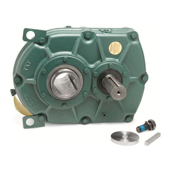
NOTE: A Screw Conveyor Drive consists of two
subassemblies and drive shaft listed below.
Reducer – Includes speed reducer, shaft retainer,
1.
retainer bolt and lockwasher.
Adapter Assembly – Includes adapter bolts,
2.
lockwashers, a lip type seal, a seal retaining ring and
drive shaft key.
Make certain none of the parts have been damaged in
shipment. Any shipping damage should be promptly
reported to the carrier. Read all instructions in this
manual before attempting to assemble or install the
Screw Conveyor Drive. It is important that assembly
be performed in the following sequence and that each
step be completed before continuing to the next.
WARNING: Because of the possible danger to person(s) or
property from accidents which may result from the improper
use of products, it is important that correct procedures be
followed. Products must be used in accordance with the
engineering information specified in the catalog. Proper
installation, maintenance and operation procedures must
be observed. The instructions in the instruction manuals
must be followed. Inspections should be made as necessary
to assure safe operation under prevailing conditions. Proper
guards and other suitable safety devices or procedures as
may be desirable or as may be specified in safety codes
should be provided, and are neither provided by ABB nor
are the responsibility of ABB. This unit and its associated
equipment must be installed, adjusted and maintained by
qualified personnel who are familiar with the construction
and operation of all equipment in the system and the
potential hazards involved. When risk to persons or property
may be involved, a holding device must be an integral part
of the driven equipment beyond the speed reducer output
shaft.
NOTE: This reducer is compatible with the ABB Ability
Smart Sensor that can be installed in the adapter plug
labeled "smart sensor". The plug and sensor can be moved
to different locations as required by mounting position.
Place reducer on blocks so that it lays flat with the
1.
input shaft down.
Position adapter on reducer output hub so that small
2.
end (end with 12 holes) rests on reducer. Select the 4
mounting holes to match the shaft used (Figure 1).
Place adapter screws and lockwashers through
3.
adapter and thread into reducer. Do not tighten.
Place seal in adapter so that spring faces out. Seal
4.
should be tapped evenly into place in the adapter
with a soft hammer, applying force only on the outer
corner of the seal. Fill cavity between lips of seal
with grease. Install seal retainer ring by tapping with
a hammer. Apply grease to adapter section of shaft
(middle section). Slide shaft, keyseated end first, into
adapter and through reducer.
NOTE: Be extremely careful when sliding adapter
section of shaft through seal to prevent seal lips from
being damaged or rolled over.
Carefully place reducer on its side. Rotate shaft to
5.
align keyseats in shaft and output hub and install key.
Install shaft retainer, lockwasher and bolt. Tighten
bolt to torque specified in Table 4.
Lay reducer on blocks with input shaft down and
6.
tighten adapter bolts to torque specified in Table 4.
If waste packing is to be used, it may be installed
7.
through access hole provided in the adapter. Waste
packing, not furnished with the screw conveyor
drive, may be used as a separate seal option or in
combination with the lip seal.
1
ASSEMBLY
Advertisement

Subscribe to Our Youtube Channel
Related Manuals for ABB Dodge HSCXT105


Summary of Contents for ABB Dodge HSCXT105
- Page 1 Please see baldor.com for updated instruction manuals. Note! The manufacturer of these products, Baldor Electric Company, became ABB Motors and Mechanical Inc. on March 1, 2018. Nameplates, Declaration of Conformity and other collateral material may contain the company name of Baldor Electric Company and the brand names of Baldor-Dodge and Baldor-Reliance until such time as all materials have been updated to reflect our new corporate identity.
- Page 2 OPTIONAL ADJUSTABLE PACKING Adjustable ADAPTER – ASSEMBLY Packing Adjustable Adapter Flange Place reducer on blocks so that it lays flat with the input shaft down. Position adapter on reducer output hub so that small end Screw (end with 12 holes) rests on reducer. Select the 4 mounting Stud holes to match the shaft used (Figure 1).
-
Page 3: Installation
INSTALLATION Install motor, drive sheave and driven sheave so that driven sheave is as close to the reducer housing as practical. Determine the running positions of the reducer (Figure 3). Install V-belt and tension with the four adjusting screws Note that the reducer is supplied with 7 plugs; 5 around provided on the SCD Motor Mount. - Page 4 Table 1 - Oil Volumes Volume of Oil Required to Fill Reducer to Oil Level Plug Reducer Position A Position B Position C Position D Position E Position F Size Fluid Fluid Fluid Fluid Fluid Fluid...
- Page 5 When Placing the Reducer Into Service: Assemble the vent plug into the proper hole. Clean the shaft extensions with petroleum solvents. Fill the unit to the proper oil level using a recommended lubricant. VCI oil will not affect the new lubricant. Follow the installation instructions provided in this manual.
- Page 6 OIL VISCOSITY EQUIVALENCY CHART KINEMATIC SAYBOLT VISCOSITIES VISCOSITIES cSt/ cSt/ AGMA GRADES SUS/ SUS/ 40°C 100°C GRADES GEAR OILS 100°F 210°F 2000 10,000 8000 1500 6000 1000 5000 1000 4000 3000 2000 1500 1000 VISCOSITIES CAN BE RELATED HORIZONTALLY ONLY. VISCOSITIES BASED ON 96 VI SINGLE GRADE OILS.
-
Page 7: Replacement Of Parts
REPLACEMENT OF PARTS REASSEMBLY: Dodge is prepared to repair Screw Conveyor Drive speed Output Hub Assembly: Heat gear to 325ºF to 350ºF to reducers for customers who do not have the proper facilities or shrink onto hub. Heat bearings to 270ºF to 290ºF to shrink for those who desire factory service. - Page 8 Table 5 - Recommended Torque Values Recommended Torque (ft.–lbs.) Torque-Arm Reducer Drive Countershaft RH Countershaft Size OP Hub Seal Hydroil Motor Backstop Adapter Bolts Housing Bolts Bearing Bearing Carrier Bolts Adapter Screws Cover Bolts Carrier Bolts Cover Screws (H)SCXT105 27–30 27–30 (H)SCXT205 45–50...
- Page 9 Figure 6 - Parts for SCXT105, SCXT205, HSCXT105 & HSCXT205 Screw Conveyor and Hydroil Screw Conveyor Drive NOTE: Parts for HSCXT Screw Conveyor Drives are the same as for SCXT Screw Conveyor Drives, except as noted in this view. Figure 7 - HSCXT105 and HSCXT205...
- Page 10 Table 7 - Parts for SCXT105, SCXT205, HSCXT105 & HSCXT205 Screw Conveyor and Hydroil Screw Conveyor Drive Reference Name of Part Number Required (H)SCXT105 (H)SCXT205 SCXT Housing 351235 352179 HSCXT Housing 351241 352246 Air Vent 900287 900287 Housing Bolt 411418 411418 ...
- Page 11 Table 7 - Parts for SCXT105, SCXT205, HSCXT105 & HSCXT205 Screw Conveyor and Hydroil Screw Conveyor Drive Reference Name of Part Number Required (H)SCXT105 (H)SCXT205 1-1/2" Dia. 351094 352090 2" Dia. 351095 352091 Drive Shaft 2-7/16" Dia. 351096 352092 3"...
- Page 12 Figure 8 - Parts for SCXT305A, SCXT405A, SCXT505A & HSCXT305A, HSCXT405A & HSCXT505A Screw Conveyor and Hydroil Screw Conveyor Drive NOTE: Parts for HSCXT Screw Conveyor Drives are the same as for SCXT Screw Conveyor Drives, except as noted in this view. Figure 9 - HSCXT305A, HSCXT405A and HSCXT505A...
- Page 13 Table 8 - Parts for SCXT305A, SCXT405A, SCXT505A & HSCXT305A, HSCXT405A & HSCXT505A Screw Conveyor and Hydroil Screw Conveyor Drive Reference Name of Part Number Required (H)SCXT305A (H)SCXT405A (H)SCXT505A (H)SCXT Housing 253169 254220 255220 Air Vent 900287 900287 904287 Housing Bolt 411440 411442...
- Page 14 Figure 10 - Parts for SCXT605 - SCXT705 Screw Conveyor Drive...
- Page 15 Table 9 - Parts for SCXT605 - SCXT705 Screw Conveyor Drive Reference Name of Part Number Required SCXT605 SCXT705 SCXT Housing Assembly 246174 247184 Air Vent 904287 390061 Housing Bolt 411466 411498 Lockwasher 419013 034017020AB Washer 419096 419082 Hex Nut 407091 407095...
- Page 16 ABB Motors and Mechanical Inc. 5711 R. S. Boreham Jr. Street Fort Smith, AR 72901 Ph: 1.479.646.4711 *1638-1019* Mechanical Power Transmission Support Ph: 1.864.297.4800 new.abb.com/mechanical-power-transmission baldor.com © ABB Motors and Mechanical Inc. All Rights Reserved. Printed in USA. MN1638 (Replaces 499375) 10/2019...
Need help?
Do you have a question about the Dodge HSCXT105 and is the answer not in the manual?
Questions and answers