Table of Contents
Advertisement
Quick Links
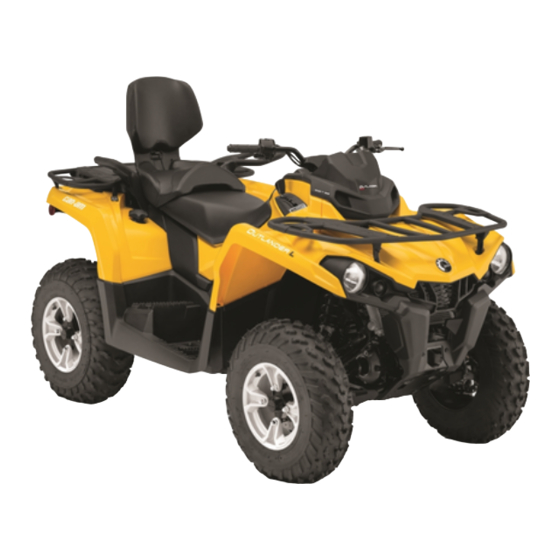
2017
T3 4x4 OUTLANDER
/
TM
OUTLANDER
MAX
TM
TM
450/570 Series
WARNING
Read this guide thoroughly. It contains important safety information.
Minimum recommended age: Operator: 16 years old. Driving tractor requires at least a tractor
driving license. Keep this Operator's Guide in the vehicle.
2 1 9
0 0 1
7 6 8
Original Instructions
Advertisement
Table of Contents
Troubleshooting


Need help?
Do you have a question about the Can-Am 450 Series and is the answer not in the manual?
Questions and answers