Advertisement
Quick Links
Installation And Maintenance Instructions
SPECIFICATIONS
Normal Operating Voltage:
Stand-By Current:
Alarm Current:
Temperature Range:
Humidity:
Dimensions:
Accessories:
Wire Gauge:
Maximum IDC Wiring Resistance:
External Power Supply Voltage:
Ripple Voltage:
IDC (supervised and power limited)
DC Voltage:
Frequency:
Current:
BEFORE INSTALLING
If the modules will be installed in an existing operational system,
inform the operator and local authority that the system will be tem-
porarily out of service. Disconnect the power to the control panel
before installing the modules. This system contains static sensitive
components. Always ground yourself with a proper wrist strap be-
fore handling any circuits so that static charges are removed from the
body. The module housing should also be grounded.
NOTICE: This manual should be left with the owner/user
of this equipment.
GENERAL DESCRIPTION
The XP6-MA Six Zone Interface Module is intended for use in an
intelligent alarm system. Each module provides an interface be-
Compatible Two-wire System Sensor Smoke Detectors for use with XP6-MA with Zone Identifier A
N500-80-00
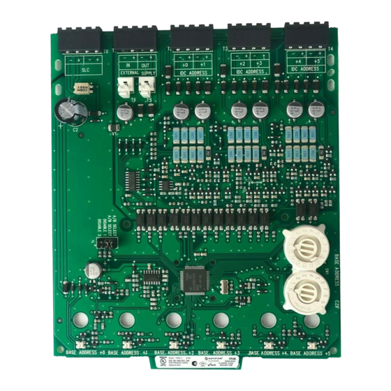
XP6-MA Six Zone Interface Module
15-32VDC
2 mA
40 mA (assumes all six LEDs solid on)
32ºF to 120ºF ( 0ºC to 49ºC)
10 to 93% Non-condensing
6.8˝H x 5.8˝W x 1.0˝D
CHS-6 Chassis; BB-25 Cabinet; BB-XP Cabinet; CAB-4 Series Cabinets; CAB-3 Series Cabinets
12-18 AWG
25 Ohms
Regulated 24VDC
0.1 volts RMS maximum
18-28 volts power limited
DC
90mA per circuit
DET.
DETECTOR
M ODEL
COMP. ID
MANUFACTURER
1151
A
SYSTEM SENSOR
1451
A
SYSTEM SENSOR
1451DH
A
SYSTEM SENSOR
2151
A
SYSTEM SENSOR
2451
A
SYSTEM SENSOR
2451TH
A
SYSTEM SENSOR
5451
A
SYSTEM SENSOR
1100
A
SYSTEM SENSOR
1400
A
SYSTEM SENSOR
** 2 100AT
A
SYSTEM SENSOR
2100B
A
SYSTEM SENSOR
2100D
A
SYSTEM SENSOR
2100S
A
SYSTEM SENSOR
2100TB
A
SYSTEM SENSOR
2100TD
A
SYSTEM SENSOR
2100TS
A
SYSTEM SENSOR
2300B
A
SYSTEM SENSOR
2300TB
A
SYSTEM SENSOR
2400
A
SYSTEM SENSOR
2400TH
A
SYSTEM SENSOR
* 2W-B
A
SYSTEM SENSOR
* 2W-TB
A
SYSTEM SENSOR
D H100LP
A
SYSTEM SENSOR
* Class B, Style B only
** No Accessory will be supported by 2100AT
tween the intelligent alarm system and a conventional alarm sys-
tem loop. A common SLC input is used for all modules, and the
initiating device loops share a common supervisory supply and
ground. Otherwise, each monitor operates independently from the
others. Each module has its own unique address.
A pair of rotary code switches is used to set the address of the first
module from 01 to 154. The remaining modules are automatically
assigned to the next five higher addresses. Provisions are included
for disabling a maximum of two unused modules to release the
addresses to be used elsewhere. Each module also has panel con-
trolled bicolor LED indicators. The panel can cause the LEDs to
blink, latch on, or latch off.
BASE MODEL
B110LP, B401
B401, B401B
DH400
B110LP, B401
DH400, B401B, B401
B401, B401B
B401
N/A
N/A
N/A
N/A
N/A
N/A
N/A
N/A
N/A
N/A
N/A
N/A
N/A
N/A
N/A
N/A
1
Notifier, 12 Clintonville Rd., Northford, CT 06472-1653 Phone: (203)484-7161
MAX DET.
20
20
20
20
20
20
20
20
20
20
20
20
20
20
20
20
20
20
20
20
20
20
20
I56-1806-006
Advertisement

Related Manuals for Notifier XP6-MA


Summary of Contents for Notifier XP6-MA
- Page 1 GENERAL DESCRIPTION trolled bicolor LED indicators. The panel can cause the LEDs to The XP6-MA Six Zone Interface Module is intended for use in an blink, latch on, or latch off. intelligent alarm system. Each module provides an interface be- Compatible Two-wire System Sensor Smoke Detectors for use with XP6-MA with Zone Identifier A DET.
-
Page 2: Compatibility Requirements
Holes Following are descriptions of the XP6-MA mounting frameworks. There are two mounting options for XP6-MA modules: • Up to six XP6-MA modules can be installed on a CHS-6 in a CAB-3 Series, CAB-4 Series or BB-25 cabinet C0235-00 •... -
Page 3: Wiring Notes
FACP manual. ordinances, and regulations. 1. Install module wiring in accordance with the job drawings and appropriate wiring diagrams. 2. All wiring to the XP6-MA is done via terminal blocks. In order to properly make electrical connections strip approximately N500-80-00 I56-1806-006... - Page 4 INSTALL DETECTORS PER MANUFACTURER'S INSTALLATION INSTRUCTIONS. FOR WIRE REQUIREMENTS. C0154-02 1. To use a common power supply between multiple XP6-MA modules, connect a long power supply jumper from T5 or T6 to T5 or T6 on the adjacent XP6-MA module. Figure 9. Interface two-wire conventional detectors – Class A, Style D:...
- Page 5 – Increase the separation between the equipment and receiver. – Connect the equipment into an outlet on a circuit different from that to which the receiver is connected. – Consult the dealer or an experienced radio/TV technician for help. N500-80-00 I56-1806-006 ©2006 Notifier...
Need help?
Do you have a question about the XP6-MA and is the answer not in the manual?
Questions and answers