Table of Contents
Advertisement
Quick Links
GENERAL
Four different monitor modules are available for NOTIFIER in-
telligent controls to suit a variety of applications. Monitor mod-
ules are used to supervise a circuit of dry-contact input de-
vices, such as conventional heat detectors and pull stations,
or monitor and power a circuit of two-wire smoke detectors
(FZM-1).
FMM-1
— is a standard-sized module (typically mounts to
a 4" [10.16 cm] square box) that supervises either a Class A
(Style D) or Class B (Style B) circuit of dry-contact input de-
vices.
FMM-101
— is a miniature monitor module (a mere 1.3"
(3.302 cm) H x 2.75" (6.985 cm) W x 0.5" (1.270 cm) D) used
to supervise a Class B (Style B) circuit. Its compact design
allows the FMM-101 to often be mounted in a single-gang
box behind the device it's monitoring.
FZM-1
— is a standard-sized module used to monitor and
supervise compatible two-wire, 24 volt, smoke detectors on
a Class A (Style D) or Class B (Style B) circuit.
FDM-1
— is a standard-sized dual monitor module used to
monitor and supervise two independent two-wire initiating
device circuits (IDCs) at two separate, consecutive addresses
in intelligent, two-wire systems.
FlashScan®
(U.S. Patent 5,539,389) is a new communi-
cation protocol developed by NOTIFIER Engineering that
greatly enhances the speed of communication between ana-
log intelligent devices. Intelligent devices communicate in a
grouped fashion. If one of the devices within the group has
new information, the panel CPU stops the group poll and
concentrates on single points. The net effect is response
speed greater than five times that of other designs.
FlashScan® is a registered trademark of NOTIFIER.
FMM-1 MONITOR MODULE
• Built-in type identification automatically identifies this de-
vice as a monitor module to the control panel.
• Powered directly by two-wire SLC loop. No additional power
required.
• High noise (EMF/RFI) immunity.
• SEMS screws with clamping plates for ease of wiring.
• Direct-dial entry of address: 01 – 159 on FlashScan® sys-
tems, 01 – 99 on CLIP systems.
• LED flashes green during normal operation (this is a pro-
grammable option) and latches on steady red to indicate
alarm.
The FMM-1 Monitor Module is intended for use in intelli-
gent, two-wire systems, where the individual address of each
module is selected using the built-in rotary switches. It pro-
vides either a two-wire or four-wire fault-tolerant Initiating
Device Circuit (IDC) for normally-open-contact fire alarm and
supervisory devices. The module has a panel-controlled LED
indicator. The FMM-1 can be used to replace MMX-1 mod-
ules in existing systems.
NOTIFIER® is a Honeywell company.
This document is not intended to be used for installation purposes. We try to keep our
product information up-to-date and accurate. We cannot cover all specific applications
or anticipate all requirements. All specifications are subject to change without notice.
For more information, contact NOTIFIER. Phone: (203) 484-7161 FAX: (203) 484-7118
12 Clintonville Road, Northford, Connecticut 06472
August 23, 2004
FMM-1, FMM-101, FZM-1, FDM-1
Monitor Modules
Monitor Modules
Monitor Modules
Monitor Modules
Monitor Modules
with FlashScan®
with FlashScan®
with FlashScan®
with FlashScan®
with FlashScan®
Section: Intelligent/Addressable Devices
CS669
S635
U.S. Coast Guard
161.002/23/3
FMM-1/-101, FZM-1)
161.002/42/1
California
(NFS-640: FMM-1/-101)
State Fire
Marshal
7300-0028:202
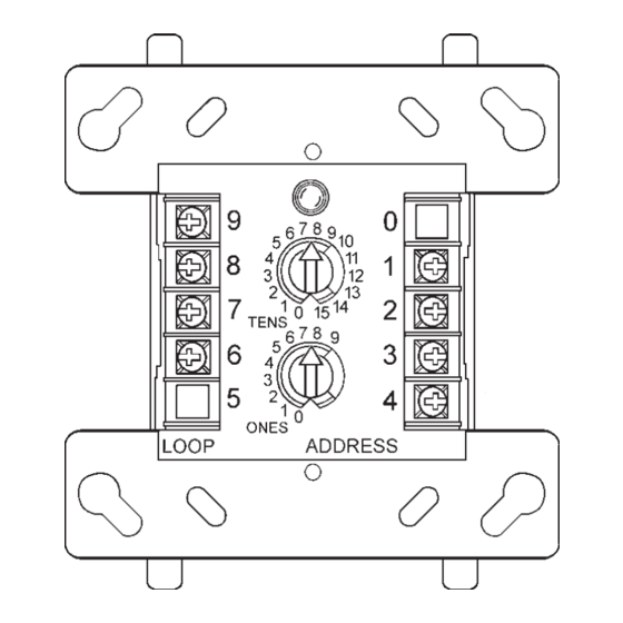
detail of FDM-1
— note "ones"
addresses are
0, 2, 4, 6, 8 only
FMM-1 Applications
wire smoke detectors, manual fire alarm pull stations,
waterflow devices, or other normally-open dry-contact alarm
activation devices. May also be used to monitor normally-
open supervisory devices with special supervisory indica-
tion at the control panel. Monitored circuit may be wired as
an NFPA Style B (Class B) or Style D (Class A) Initiating
Device Circuit. A 47K ohm End-of-Line Resistor (provided)
terminates the Style B circuit. No resistor is required for su-
pervision of the Style D circuit. Maximum IDC loop length is
2,500 ft./762 m (20 ohms maximum).
DN-6720 • H-220
93/60141 (E3)
(FMM-1/-101, FZM-1)
94/60004/E2
(AFP-200:
(AFP200:
except FDM-1)
02/60007
(NFS-640: FDM-1)
MEA
143-01-E
(FDM-1)
317-01-E
(FMM-1/-101)
345-02-E
(FMM-1/-101)
457-99-E
(FZM-1,
FMM-1/-101)
447-99-E
FMM-1
and
FZM-1
— Use to monitor a zone of four-
DN-6720 • 08/23/04 — Page 1 of 6
Advertisement
Table of Contents

Related Manuals for Notifier FMM-1 FlashScan


Summary of Contents for Notifier FMM-1 FlashScan
- Page 1 We cannot cover all specific applications or anticipate all requirements. All specifications are subject to change without notice. For more information, contact NOTIFIER. Phone: (203) 484-7161 FAX: (203) 484-7118 12 Clintonville Road, Northford, Connecticut 06472...
- Page 2 FMM-1 Operation — Each FMM-1 uses one of 159 avail- regular polls from the control panel and reports its type and the status (open/normal/short) of its Initiating Device Circuit able module addresses on an SLC loop. It responds to regu- lar polls from the control panel and reports its type and the (IDC).
- Page 3 — The FDM-1 auto- SPECIFICATIONS matically assigns itself to two addressable points, starting Specifications of these and all NOTIFIER products are avail- with the original address. For example, if the FDM-1 is set to able from NOTIFIER. address “56”, then it will automatically assign itself to ad- dresses “56”...
-
Page 4: Wiring Diagrams
WIRING DIAGRAMS The following wiring diagrams are included: FDM-1, typical dual two-wire Style B initiating device circuit configuration. FMM-101, typical two-wire Style B initiating device circuit configuration. FMM-1, typical two-wire initiating circuit configuration, NFPA Style B. FMM-1, typical four-wire fault-tolerant initiating circuit configuration, NFPA Style D. FMM-1, typical two-wire initiating circuit configuration for security systems (with alarm versus short capability). - Page 5 WIRING DIAGRAMS THIS PAGE: FMM-1 • Connect modules to listed compatible NOTIFIER control panels only. • All wiring shown is supervised and power limited. • Install contact closure devices per manufacturers’ installation instructions. • Any number of UL-listed contact closure devices may be used.
- Page 6 • Connect modules to listed compatible control panels only. WIRING • Terminal wiring must be power limited. DIAGRAMS • DO NOT MIX fire alarm initiating, supervisory, or security devices on the same circuit. THIS PAGE: • DO NOT LOOP wire under terminals. Break wire run to provide supervision of connections. •...
Need help?
Do you have a question about the FMM-1 FlashScan and is the answer not in the manual?
Questions and answers