Advertisement
Quick Links
1 Product Overview
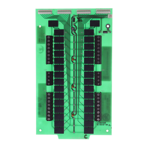
The LDM Lamp Driver Modules (LDM-32, LDM-E32, and LDM-R32) are used to drive lamps or LEDs in a
custom mimic connected to an addressable fire panel.
2 Installation
WARNING: Remove all power sources to the panel before installation. Leave the
external and main power OFF until installation is complete.
2.1 Mounting a LDM Module to a CHS Chassis
1. Screw two 3/4" stand-offs onto the mounting studs of a CHS chassis.
2. Place the module on the CHS chassis. Ensure the tab on the module slides into the slot on the
CHS chassis.
3. Secure the module with two 4-40 screws.
2.2 Mounting a LDM Relay Expander
The LDM-R32 can either be mounted alongside a LDM module or expander in the CHS chassis (see
section 2.1 for CHS mounting), or stacked on top of a LDM module using the standoffs provided (see Figure
2-2.)
Make sure to connect the Relay Power Ribbon Cable between the LDM-R32 and the LDM Module, as
shown in Figure 2-3.
Installation Sheet - Released
Figure 2-1 - Mounting the LDM to a CHS Chassis
PH 02-9894-1444 • FAX 02-9894-4193
LDM Lamp Driver
26/03/2015
9 Columbia Way
Baulkham Hills, NSW 2153
www.notifier.com.au
Rev A
DOC-03-091
Page 1 of 4
Advertisement

Summary of Contents for Notifier LDM-32
-
Page 1: Product Overview
Rev A DOC-03-091 1 Product Overview The LDM Lamp Driver Modules (LDM-32, LDM-E32, and LDM-R32) are used to drive lamps or LEDs in a custom mimic connected to an addressable fire panel. 2 Installation WARNING: Remove all power sources to the panel before installation. Leave the external and main power OFF until installation is complete. - Page 2 Relay Power Ribbon Cable connection LDM-32 (or LDM-E32) LDM-R32 9.;> >=D2? Standoff Standoff Chassis LDM-R32 LDM-32 (or LDM-E32) Figure 2-2 – Mounting a LDM-R32 on top of Figure 2-3 - Connecting the Relay Power Ribbon Cable a LDM Module 2.3 Connections NOTE: When cables are not run in a conduit, shielding on cables for EIA-485 connections must be grounded outside the enclosure and fire panel.
- Page 3 1. Set a unique address for the LDM-32 using the rotary address switches along the side of the module. 2. Set the operating mode using the DIP switches on the LDM-32. See Table 1 for a description of the switch functions.
- Page 4 XLS-3000A Australian Programming Manual DOC-01-035 XLS-3000A New Zealand Programming Manual DOC-01-041 DOC-01-043 Notifier NCA-2 Australian Manual DOC-01-045 Notifier NCA-2 New Zealand Manual DOC-01-044 Honeywell NCA-2 Australian Manual DOC-01-046 Honeywell NCA-2 New Zealand Manual Table 3 - Supplemental Documentation Page 4 of 4...


Need help?
Do you have a question about the LDM-32 and is the answer not in the manual?
Questions and answers