Table of Contents
Advertisement
Quick Links
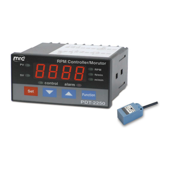
RPM CONTROLLER
MONITOR
Model : PDT-2250
Your purchase of this RPM CONTROLLER/MONITOR marks
a step forward for you into the field of precision
measurement. Although this CONTROLLER is a complex
and delicate instrument, its durable structure developed.
Please read the following instructions carefully and
always keep this manual within easy reach.
PLEASE READ THIS MANUAL CAREFULLY BEFORE OPERATION
3, Hagavish st. Israel 58817 Tel: 972 3 5595252, Fax: 972 3 5594529
OPERATION MANUAL
MRC.11.20
mrc@mrclab.com
Advertisement
Table of Contents

Related Manuals for MRC PDT-2250


Summary of Contents for MRC PDT-2250
- Page 1 RPM CONTROLLER MONITOR Model : PDT-2250 Your purchase of this RPM CONTROLLER/MONITOR marks a step forward for you into the field of precision measurement. Although this CONTROLLER is a complex and delicate instrument, its durable structure developed. Please read the following instructions carefully and always keep this manual within easy reach.
-
Page 2: Caution Symbol
Caution Symbol Caution : * Risk of electric shock ! Caution : * Do not use fingers or any tool to touch the Wire Terminals. * Do not apply the relay contact load current > 0.5 Amp. * The instrument contains no user serviceable parts and should not be opened by the user. - Page 3 TABLE OF CONTENTS 1. FEATURES..............1 2. SPECIFICATIONS............1 2-1 General Specifications...........1 2-2 Electrical Specifications.........3 3. FRONT PANEL DESCRIPTION........4 3-1 Display..............4 3-2 PV ( process value ) indicator........4 3-3 SV ( set value ) indicator........4 3-4 Set Button............4 Button.............
-
Page 4: Specifications
1. FEATURES * Professional Tachometer ( RPM, m/min., ft/min. ) monitor and controller. * Build in control relay and the alarm relay. * Alarm Relay will make action when the reading value reach to high/low alarm value. * Control Relay will make action when the reading value reach to control value. - Page 5 Sampling Time Approx. 1 second. * Input : one pulse per round, 60 RPM ≧ Relay Output Number 2 relays Relay 1 : Function Control relay. Relay 2 : High/Low alarm relay. Max load 0.5 ACA/250 ACV 0.5 DCA/24 DCV * Do not apply the relay contact load current >...
- Page 6 Accessories Instruction manual......1 PC Included Case holder with screw....2 PCs Optional * Proximity sensor, PX-01. Accessories * Photo sensor, PI-06. * Data Acquisition software, SW-U801-WIN. * RS232 cable, UPCB-02. * USB cable, USB-01. * GSM controller, GSM-889. * Interface cable ( cable between meter to GSM-889 ), GMCB-89.
-
Page 7: Front Panel Description
3. FRONT PANEL DESCRIPTION Fig. 1 3-1 Display 3-2 PV ( process value ) indicator 3-3 SV ( set value ) indicator 3-4 Set Button Button ▼ Button ▲ 3-7 Function Button 3-8 Control relay indicator 3-9 Alarm relay indicator 3-10 RPM indicator 3-11 ft/min indicator 3-12 m/min indicator... -
Page 8: Measuring Procedure
4. MEASURING PROCEDURE Terminal layout Fig. 2 4-1 Terminal connection 1) Input the ACV power ( 90 to 260 ACV ) to T1, T2. Do not input the over voltage to the AC input terminals. 2) Connect the " Control Relay " output from T3, T4. Connect the "... - Page 9 4-2 RPM measurement 1) Power on the meter, the " Display " ( 3-1, Fig. 1 ). 2) Press the " Function Button " ( 3-7, Fig. 1 ) once until the " RPM indicator " ( 3-10, Fig. 1 ) and the " PV indicator "...
- Page 10 The m/min. value equal : Total input signal ( pulse ) per min. ÷ ( divide ) setting pulse no. per round x ( multiple ) setting roller diameter ( cm ) x ( multiple ) 3.14 ÷ ( divide ) 1 meter = 100 cm For example : If the total input signal ( pulse ) per minute...
- Page 11 For example : If the total input signal ( pulse ) per minute is 501, the setting pulse no. per round is 1, the roller diameter is 10 cm the ft/min. value will be 501/1x10x3.14/30.48=516.1 * The procedures that to set the "...
- Page 12 Low Limit Value Setting 1) Press the " Set Button " ( 3-4, Fig. 1 ) twice, the " Display " will show " LoLt ", now the meter is ready " Low Limit value " setting. 2) Use the " " Button "...
- Page 13 Consideration of 1st layer setting 1) Under the normal " Display ", if the " Function Button " ( 3-7, Fig. 1 ) select to " RPM function ", the " RPM indicator " ( 3-10, Fig. 1 ) light, the " 1st layer setting "...
- Page 14 Remark : * When adjust the value, the " SV indicator " ( 3-3, Fig. 1 ) will light. * The function of " Pulse no. per round setting ", refer to page 6, 7. Roller diameter value setting 1) After set the " Pulse no. per round ", press the "...
- Page 15 Fig. 3 * For example : Control value : 500 Control Hysteresis value : 5 The control relay will On when measuring value up to 500. The control relay will Off again when measuring value down to 495. Alarm Hysteresis value setting 1) After select the "...
- Page 16 Fig. 4 * For example : High limit value : 100 Low limit value : 20 Alarm Hysteresis value : 5 a. The alarm relay will On when measuring value up to 100. The alarm relay will Off again when measuring value down to 95. b.
-
Page 17: Rs232 Pc Serial Interface
5. RS232 PC SERIAL INTERFACE The instrument has RS232 PC serial interface via a 3.5 mm terminal ( 3-15, Fig. 1 ). The data output is a 16 digit stream which can be utilized for user's specific application. A RS232 lead with the following connection will be required to link the instrument with the PC serial port. -
Page 18: System Reset
Each digit indicates the following status : Start Word When send the upper display data = 1 When send the lower display data = 2 D12 & D11 Annunciator for Display RPM = 27 ft/min = 11 m/min = 60 Polarity 0 = Positive 1 = Negative Decimal Point(DP), position from right to the... - Page 19 7. OPTIONAL PROXIMITY SENSOR Model : PX-01 Application * Sensor for PDT-2250 Panel RPM Controller, Monitor * Sensor for DT-2240D Panel Tachometer * Position Detector. Output method PNP, NO(normal open) Sensing direction Vertical. Sensing distance 4 mm. Operating voltage 10-30 VDC.
Need help?
Do you have a question about the PDT-2250 and is the answer not in the manual?
Questions and answers