Sony MHC-V6D Service Manual
Hide thumbs Also See for MHC-V6D:
Table of Contents

Advertisement

SERVICE MANUAL
Ver. 1.4 2015.05
Note:
Be sure to keep your PC used for service and
checking of this unit always updated with the
latest version of your anti-virus software.
In case a virus affected unit was found during
service, contact your Service Headquarters.
Amplifier section
iPod/iPhone section
Power output (rated):
Made for
Left/Right Channel: 320 W +
– iPhone 5s
320 W (at 5 ohms, 1 kHz, 1% THD)
– iPhone 5c
Power output (reference):
– iPhone 5
Left/Right Channel: 480 W +
– iPhone 4s
– iPhone 4
480 W (per channel at 5 ohms,
1 kHz)
– iPhone 3GS
Subwoofer: 480 W (at 5 ohms,
– iPod touch (5th generation)
100 Hz)
– iPod touch (4th generation)
Speaker section
Disc player section
Speaker system: Tweeter + Mid range
System:
speaker + woofer
Compact disc and digital audio
Tweeter L/R: 40 mm cone type
and video system
Mid L/R: 100 mm cone type
Laser Diode Properties
Woofer: 250 mm cone type
Emission Duration: Continuous
Laser Output*: Less than 44.6 μW
Inputs
* This output is the value
AUDIO IN/PARTY CHAIN IN L/R:
measurement at a distance of
Voltage 2 V, impedance
200 mm from the objective lens
surface on the Optical Pick-up
47 kilohms
Block with 7 mm aperture.
MIC 1, MIC 2:
Frequency response:
Sensitivity 1 mV, impedance
20 Hz - 20 kHz
10 kilohms
Signal-to-noise ratio:
A (USB),
B (USB) port:
More than 90 dB
Type A, maximum current:
Dynamic range:
500 mA
More than 88 dB
Outputs
Video color system format:
AUDIO OUT/PARTY CHAIN OUT L/R:
NTSC and PAL
Voltage 2 V, impedance
47 kilohms
VIDEO OUT:
Max. output level 1 Vp-p,
unbalanced, Sync. negative load
impedance 75 ohms
9-893-996-05
Sony Corporation
2015E33-1
©
2015.05
Published by Sony Techno Create Corporation
Model Name Using Similar Mechanism
DVD Mechanism Type
Optical Pick-up Block Name
SPECIFICATIONS
Tuner section
BLUETOOTH section
FM stereo, FM/AM superheterodyne
Communication system:
tuner
BLUETOOTH Standard version 3.1
Antenna:
Output:
FM lead antenna
BLUETOOTH Standard Power
AM loop antenna
Class 2
Maximum communication range:
FM tuner section
Line of sight approx. 10 m
Tuning range:
Frequency band:
87.5 MHz - 108.0 MHz (50 kHz
2.4 GHz band (2.4000 GHz –
step)
2.4835 GHz)
Modulation method:
AM tuner section
FHSS (Freq Hopping Spread
Tuning range:
Spectrum)
Latin American model:
Compatible BLUETOOTH profiles
530 kHz – 1,710 kHz (10 kHz step)
A2DP (Advanced Audio
531 kHz – 1,710 kHz (9 kHz step)
Distribution Profile)
Other models:
AVRCP 1.3 (Audio Video Remote
531 kHz – 1,602 kHz (9 kHz step)
Control Profile)
530 kHz – 1,610 kHz (10 kHz step)
SPP (Serial Port Profile)
Supported codecs:
SBC (Sub Band Codec)
AAC (Advanced Audio Coding)
1)
The actual range will vary depending
on factors such as obstacles between
devices, magnetic fields around a
microwave oven, static electricity,
reception sensitivity, antenna's
performance, operating system,
software application, etc.
2)
BLUETOOTH standard profiles
indica te the purpose of BLUETOOTH
communication between devices.
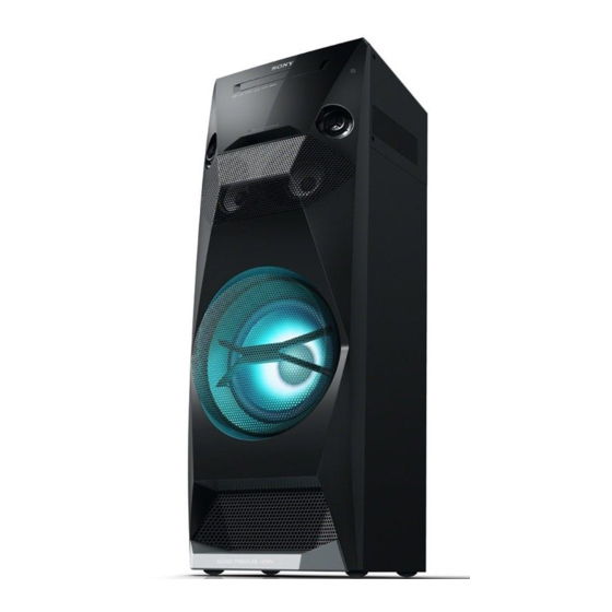
MHC-V6D
NEW
CDM90-DVBU202 or CDM90-DVBU204
CMS-S76RFS7G or CMS-S76RFS7G1
or CMS-S76RFS7GP
Supported audio formats
Supported bit rate:
MPEG1 Layer-3:
32 kbps – 320 kbps, VBR
WMA (USB devices only):
48 kbps – 192 kbps, VBR
AAC (USB devices only):
1)
48 kbps – 320 kbps, VBR
Sampling frequencies:
MPEG1 Layer-3:
32 kHz/44.1 kHz/48 kHz
WMA (USB devices only):
44.1 kHz
AAC (USB devices only):
2)
:
44.1 kHz
Supported video formats
Xvid:
Video codec: Xvid video
Bit rate: 4.854 Mbps (MAX)
Resolution/Frame rate:
720 × 480 (30 fps)
720 × 576 (25 fps)
Audio codec: MP3
MPEG4:
File format: MP4 File Format
Video codec: MPEG4 Simple
Profile (AVC is not compatible.)
Bit rate: 4 Mbps
Resolution/Frame rate:
720 × 480 (30 fps)
720 × 576 (25 fps)
Audio codec: AAC-LC (HE-AAC is
not compatible.)
DRM: Not compatible
HOME AUDIO SYSTEM
E Model
General
Power requirements:
Indian and Thai models:
AC 220 V – 240 V, 50/60 Hz
Other models:
AC 120 V – 240 V, 50/60 Hz
Power consumption:
Indian model:
195 W (0.5 W at the Power Saving
mode)
Other models:
240 W (0.5 W at the Power Saving
mode)
Dimensions (W/H/D) (Approx.):
339 mm × 908 mm × 325 mm
Mass (Approx.):
18 kg
Supplied accessories:
Remote control (1)
R6 (Size AA) batteries (2)
AC power cord (1)
FM lead/AM loop antenna (1)
Video cord (1)
Design and specifications are subject
to change without notice.

Advertisement

Table of Contents
loading

Summary of Contents for Sony MHC-V6D

  • Page 1 47 kilohms Audio codec: AAC-LC (HE-AAC is VIDEO OUT: not compatible.) Max. output level 1 Vp-p, DRM: Not compatible unbalanced, Sync. negative load impedance 75 ohms HOME AUDIO SYSTEM 9-893-996-05 Sony Corporation 2015E33-1 © 2015.05 Published by Sony Techno Create Corporation...
  • Page 2 NO LICENSE IS GRANTED OR SHALL facility and give the owned by Bluetooth SIG, Inc. and 5-character service BE IMPLIED FOR ANY OTHER any use of such marks by Sony number. USE. ADDITIONAL INFORMATION Corporation is under license. Other Example: E 61 10...
  • Page 3: Table Of Contents

    MHC-V6D TABLE OF CONTENTS SERVICING NOTES 5-7. Schematic Diagram - MAIN Section (3/9) - ....47 ..........5-8. Schematic Diagram - MAIN Section (4/9) - ....48 DISASSEMBLY 5-9. Schematic Diagram - MAIN Section (5/9) - ....49 5-10. Schematic Diagram - MAIN Section (6/9) - ....50 2-1.
  • Page 4: Servicing Notes

    MHC-V6D SECTION 1 SERVICING NOTES TEST DISCS NOTES ON HANDLING THE OPTICAL PICK-UP Use following TEST DISC when this unit confi rms the operation BLOCK OR BASE UNIT and checks it. The laser diode in the optical pick-up block may suffer electro- •...
  • Page 5 MHC-V6D Ver. 1.3 CAPACITOR ELECTRICAL DISCHARGE PROCESSING MODEL IDENTIFICATION When checking the board, the electrical discharge is necessary for Distinguish by Part No. and Destination code on the rear side of the electric shock prevention. a main unit. Connect the resistor to both ends of respective capacitors.
  • Page 6 MHC-V6D HOW TO OPEN THE TRAY WHEN POWER SWITCH TURN OFF Note 1: After the side panel and top panel are removed, this work is done. Note 2: Please prepare the thin wire (clip etc. processed to the length of 8 cm or more).
  • Page 7: Disassembly

    MHC-V6D SECTION 2 DISASSEMBLY • This set can be disassembled in the order shown below. 2-1. DISASSEMBLY FLOW When disassembling the unit, use the following jig for speaker removal. Part No. Description 2-2. SIDE L, R PANEL BLOCK J-2501-238-A JIG FOR SPEAKER REMOVAL (Page 8) 2-3.
  • Page 8: Side L, R Panel Block

    MHC-V6D Note: Follow the disassembly procedure in the numerical order given. 2-2. SIDE L, R PANEL BLOCK 3 screw cap 2 claw 2 claw 1 Insert needle-nose pliers behind the second fin, and press in the direction of the arrow.
  • Page 9: Top Panel Block

    MHC-V6D 2-3. TOP PANEL BLOCK 3 Remove the top panel block Wire in the direction of the arrow. flexible flat cable (4P) 2 five claws 7 top panel block 5 flexible flat cable (4P) (CN2102) guide line guide line 1 three screws...
  • Page 10: Volume Knob Block

    MHC-V6D 2-4. VOLUME KNOB BLOCK Note 1: When installing the volume knob block, aline the two ribs of volume knob and 2 volume knob block the shaft. volume knob block – hole top panel block shaft – – 1 Push the volume knob block by flat-head screwdriver.
  • Page 11: Loading Panel Block

    MHC-V6D 2-5. LOADING PANEL BLOCK hole 3 two 2 Draw out the tray. – Left view – claws 4 loading panel block thin wire (clip etc. ) CD mechanism deck 1 Insert the clip etc. in the hole, and push the lever in the direction of the arrow.
  • Page 12: Cdm Block

    MHC-V6D 2-6. CDM BLOCK 7 CDM block Wire CDM block 6 flexible flat cable (24P) (CN302) 1 screw 5 flexible flat cable (BVTP3 (5P) (CN303) 4 connector ARAGON board (CN401) Note 1: Connect the wire from the CDM 3 Remove the CDM block block to the ARAGON board and in the direction of the arrow.
  • Page 13: Back Panel Block

    MHC-V6D 2-7. BACK PANEL BLOCK fa wire etti CN1003 coating clip 1 Remove the DC fan wire from the coating clip. DC fan hole 4 connector 3 flexible flat cable (9P) (CN901) (CN851) 2 DC fan connector (CN1003) hole hook...
  • Page 14: Aragon Board-1

    MHC-V6D 2-8. ARAGON BOARD-1 • Continued on 2-9 (page 15). D-AMP board 1 cushion (H) coating clip 3 Remove the wire from the coating clip. 7 flexible flat cable (10P) (CN102) 4 connector (CN001) cushion (H) ARAGON board 2 wire flat type...
  • Page 15: Aragon Board-2

    MHC-V6D 2-9. ARAGON BOARD-2 • Continued on 2-10 (page 16). 1 cushion (H) cushion (H) FL board ARAGON board 2 flexible flat cable (8P) (CN105) 3 flexible flat cable (23P) (CN109) Note: When installing the flexible flat cable, ensure that –...
  • Page 16: Aragon Board-3

    MHC-V6D 2-10. ARAGON BOARD-3 • Abbreviation E93: United Arab Emirates, Kuwait, Iraq, Kenya, Tanzania and Nigeria models 2 coating clip (E93) 1 screw 4 filament tape (BV/RING) (sub material) 1 screw 5 sheet (BV/RING) (E93) (EMC-absober) 3 lug wire 1 three screws...
  • Page 17: D-Amp Board-1

    MHC-V6D 2-11. D-AMP BOARD-1 • Continued on 2-12 (page 18). D-AMP board [yellow] 4 connector filament tape filament tape (CN1008) (sub material) (sub material) [blue] [red] 3 connector 5 connector (CN1009) (CN1010) 2 connector (CN1000) – – 1 two filament tapes (sub material) Note: Insert the connector straight into the interior.
  • Page 18: D-Amp Board-2

    MHC-V6D 2-12. D-AMP BOARD-2 short long to D-AMP board terminal face 2 two screws 4 two screws (BV/RING) (PTPWH2.6 6 heat sink D-AMP 1 flexible flat cable (19P) board (CN1006) 2 two screws 7 thermal sheet Terminal face is (BV/RING) below side.
  • Page 19: Sub Chassis

    MHC-V6D 2-13. SUB CHASSIS 4 sub chassis 1 screw 2 two screws (PSW M3 (BV/RING) hole 2 screw (BV/RING) 2 screw 3 Draw out the wire from hole. (BV/RING) – Top rear view –...
  • Page 20: Front Panel Block-1

    MHC-V6D 2-14. FRONT PANEL BLOCK-1 • Continued on 2-15 (page 21). • Abbreviation E93: United Arab Emirates, Kuwait, Iraq, Kenya, Tanzania and Nigeria models (E93) coating clip FL board coating clip coating clip FL board FL board 1 Remove the wire from the coating clip.
  • Page 21: Front Panel Block-2

    MHC-V6D 2-15. FRONT PANEL BLOCK-2 MIC board Note 1: Pass the flexible flat cable (4P) over the top of the loudspeaker. [yellow] 4 three screws (BV/RING) 5 boss 6 front panel block [black] 5 boss 3 connector (CN2002) 5 two bosses...
  • Page 22: Switching Regulator (Swr1)

    MHC-V6D 2-16. SWITCHING REGULATOR (SWR1) 1 Remove the wire from the coating clip. switching regulator (SWR1) coating clip – Top rear view – 5 two screws 3 connector (BV/RING) 4 connector (CN401) (CN201) 5 three screws (BV/RING) 5 two screws...
  • Page 23: Front Panel (Sp) Block

    MHC-V6D 2-17. FRONT PANEL (SP) BLOCK 3 Insert the jig into the space and slowly remove the front panel (SP) block. Note: When using a jig, please work so as not to injure front panel (SP) block and speaker cabinet.
  • Page 24: Speaker Led Board, Front Panel (Sp) Assy

    MHC-V6D 2-18. SPEAKER LED BOARD, FRONT PANEL (SP) ASSY Wrap twice. 5 front panel (SP) assy cushion sleeve ferrite clamp (E 0.5) (FC5) 1 cushion (H) total six grooves cushion (H) 1 cushion (H) 3 connector (CN1800) 2 screw (BVTP3...
  • Page 25: Loudspeaker (25 Cm) (Woofer) (Sp5)

    MHC-V6D 2-19. LOUDSPEAKER (25 cm) (WOOFER) (SP5) loudspeaker (25 cm) terminal position (SP5) 3 terminal (narrow side) [black] 3 terminal (wide side) [red] 4 loudspeaker (25 cm) (woofer) (SP5) 2 Remove the loudspeaker (25 cm) (SP5) in the direction of the arrow.
  • Page 26: Loudspeaker (10 Cm) (Mid: L-Ch) (Sp1)

    MHC-V6D 2-20. LOUDSPEAKER (10 cm) (MID: L-CH) (SP1) loudspeaker (10 cm) loudspeaker groove (SP1) (10 cm) (SP1) terminal position terminal terminal (narrow side) (wide side) 4 terminal (narrow side) 4 terminal (wide side) 5 loudspeaker (10 cm) (mid: L-ch) (SP1)
  • Page 27: Loudspeaker (10 Cm) (Mid: R-Ch) (Sp3)

    MHC-V6D 2-21. LOUDSPEAKER (10 cm) (MID: R-CH) (SP3) terminal position loudspeaker (10 cm) groove (SP3) terminal (narrow side) terminal (wide side) loudspeaker (10 cm) (SP3) cushion (H) wire 5 terminal (narrow side) 1 cushion (H) 5 terminal (wide side) 6 loudspeaker (10 cm)
  • Page 28: Fl Board Block

    MHC-V6D 2-22. FL BOARD BLOCK • Abbreviation E93: United Arab Emirates, Kuwait, Iraq, Kenya, Tanzania and Nigeria models terminal face to FL board to FL board – – ferrite core (FC4) terminal face FL board filament tape (sub material) filament tape...
  • Page 29: Bluetooth Module (Bt1)

    MHC-V6D 2-23. BLUETOOTH MODULE (BT1) Wire e i – r e re r ie – filament tape (sub material) bluetooth module (BT1) 2 Remove the bluetooth module (BT1) in the direction of the arrow. 3 filament tape 1 cishion (H)
  • Page 30: Usb Board Block

    MHC-V6D 2-24. USB BOARD BLOCK • Abbreviation E93: United Arab Emirates, Kuwait, Iraq, Kenya, Tanzania and Nigeria models (E93) – Front panel rear view – Ferrite ore (F 3) ettin ferrite core (FC3) 3 Remove the USB board block guide line in the direction of the arrow.
  • Page 31: Mic Board

    MHC-V6D 2-25. MIC BOARD – Front panel rear view – 1 knob (MIC) 2 screw (BVTP3 3 MIC board 2 screw (BVTP3 2-26. NFC MODULE (NFC1) 3 Remove the NFC module block Wire e i in the direction of the arrow.
  • Page 32: Ffc Holder

    MHC-V6D 2-27. FFC HOLDER 1 two screws (BVTP3 1 two screws (BVTP3 2 CD mechanism deck block FFC holder cushion (H) 6 FFC holder Note: When installing the FFC holder, 3 cushion (H) check that installed firmly two bosses and claw.
  • Page 33: Optical Pick-Up Block (Cms-S76Rfs7G) (Op1)

    MHC-V6D 2-28. OPTICAL PICK-UP BLOCK (CMS-S76RFS7G) (OP1) e i e Terminal face is below side. 2 chuck holder block 5 insulator screw – – 0 insulator 5 insulator screw 7 connector qa optical pick-up block (CMS-S76RFS7G) 0 insulator (OP1) 5 insulator...
  • Page 34: Test Mode

    MHC-V6D SECTION 3 TEST MODE COLD RESET DISC TRAY LOCK MODE It can clears all data including preset data stored in the memory to It can be unable to take sample disc out of disc tray in the shop. initial conditions. Execute this mode when returning the this unit Procedure: to the customer.
  • Page 35 MHC-V6D Ver. 1.3 VERSION DISPLAY 6. Each time [ +PRESET+] button is pressed, tthe display changes destination → SC version → MTK version → OPU It can confi rm the SC and MTK version. version → UI version → PF version → SYS version → CD Procedure: version →...
  • Page 36 MHC-V6D DVD SERVICE MODE 8. When pressing the [ –PRESET–] button, “K 0 V0” is dis- • This mode let you make diagnosis and adjustment easily by played on the fl uorescent indicator tube. using the remote commander and the TV. The instructions, di- Screen display agnostic results, etc.
  • Page 37 MHC-V6D • Execute IOP Measurement • Check Emergency History In order to execute IOP measurement, the following standard To check the emergency history, please follow the following procedures must be followed. procedure. 1. From the Top Menu of Remocon Diagnosis Menu, select “2.
  • Page 38 MHC-V6D • Parameter of error code To clear the Initialize Setup Data This is the detail of error code. Press the [DVD/TUNER MENU] button on the remote command- er. And then while pressing the [SHIFT] button on the remote com- Example of Error code mander, press the [CLEAR] button on the remote commander.
  • Page 39: Electrical Check

    MHC-V6D SECTION 4 ELECTRICAL CHECK TUNER SECTION 0 dB = 1 V FM TUNE LEVEL CHECK signal generator unit Procedure: 1. Press the [ ] button to turn the power on. 2. Input the following signal from signal generator to FM antenna input directly.
  • Page 40: Diagrams

    MHC-V6D SECTION 5 DIAGRAMS 5-1. BLOCK DIAGRAM - CD/USB Section - OPTICAL PICK-UP BLOCK RF AMP, SERVO/AUDIO PROCESSOR (CMS-S76RFS7G) IC301 ASDATA0, MTK-BCK, MTK-LRCK, MTK-MCK ASDATA0 >001B 123 RFIP ASDATA0 MTK-BCK ABCK (Page 41) VOA/A 1 RF_C MTK-LRCK ALRCK VOB/B 128 RF_B...
  • Page 41: Block Diagram - Main Section

    MHC-V6D 5-2. BLOCK DIAGRAM - MAIN Section - DIGITAL AUDIO SELECTOR SAMPLE RATE CONVERTER ASDATA0, MTK-BCK, IC607 IC610 MTK-LRCK, MTK-MCK (Page 42) ASDATA0 >001B DOUT0 >003B 4 SDIN SDOUT 28 SSI3_DI SSI0_DO (Page 40) 5 BCKI BCKO DOUT2 DOUT0, DOUT2,...
  • Page 42: Block Diagram - Amp Section

    MHC-V6D 5-3. BLOCK DIAGRAM - AMP Section - D/A CONVERTER AUDIO AMP IC611 IC1011 (Page 41) DOUT0 BOOSTER >003B DATA VOUTL IN– Q1028 DAC LPF PRE AMP (MID) DOUT0, DOUT2, IC612 IC1015 (L-CH) ARAGON-MCK, VOUTR ARAGON-BCK0, ARAGON-BCK0 1 BCK ARAGON-LRCK0...
  • Page 43: Block Diagram - Panel/Power Supply Section

    MHC-V6D 5-4. BLOCK DIAGRAM - PANEL/POWER SUPPLY Section - SYSTEM CONTROLLER IC101 (4/4) D1024 TEMPERATURE DETECT THERMISTOR-PROTECT 78 TH1008 REMOTE CONTROL Q1066, 1067 REGULATOR GVDD –46V RECEIVER 135 SIRCS IC1002 IC2000 –5V –5V REGULATOR TH1009 ND2000 IC1001 FLUORESCENT SPM-AMBIENT-TEMP 80...
  • Page 44 MHC-V6D Ver. 1.3 THIS NOTE IS COMMON FOR PRINTED WIRING BOARDS AND SCHEMATIC DIAGRAMS. • Circuit Boards Location (In addition to this, the necessary note is printed in each block.) For Printed Wiring Boards. For Schematic Diagrams. D-AMP board Note: Note: •...
  • Page 45: Schematic Diagram - Main Section (1/9)

    MHC-V6D 5-5. SCHEMATIC DIAGRAM - MAIN Section (1/9) - • See page 68 for Waveforms. • See page 69 for IC Block Diagrams. • See page 74 for IC Pin Function Description. ARAGON BOARD (1/9) ASDATA0 FE_OPO MTK-LRCK >106S FE_OP–...
  • Page 46: Schematic Diagram - Main Section (2/9)

    MHC-V6D 5-6. SCHEMATIC DIAGRAM - MAIN Section (2/9) - • See page 69 for IC Block Diagrams. ARAGON BOARD (2/9) R415 FE_MUTE FE_TRO R418 SL402 FE_FMO R421 C403 C402 R422 0.015 330p R433 CL412 CL413 SL401 >103S FE_FOO C420 C423...
  • Page 47: 5-7. Schematic Diagram - Main Section (3/9)

    MHC-V6D 5-7. SCHEMATIC DIAGRAM - MAIN Section (3/9) - • See page 68 for Waveforms. • See page 69 for IC Block Diagrams. ARAGON BOARD (3/9) CN851 >131S JL905 JL623 R859 CVBUS IISD (data audio) ARAGON JL624 R851 DVDD5V BOARD...
  • Page 48: Schematic Diagram - Main Section (4/9)

    MHC-V6D 5-8. SCHEMATIC DIAGRAM - MAIN Section (4/9) - • See page 69 for IC Block Diagrams. ARAGON BOARD (4/9) R624 2.2k J601 JL619 Q602 IMX25T110 AUDIO OUT MUTING PARTY CHAIN OUT JL620 -3.4 C602 R653 R913 6.8k JL604 R625...
  • Page 49: Schematic Diagram - Main Section (5/9)

    MHC-V6D 5-9. SCHEMATIC DIAGRAM - MAIN Section (5/9) - • See page 69 for IC Block Diagrams. ARAGON BOARD (5/9) R626 C603 R609 4.7k 0.001 4.7k >119S R619 ARAGON C608 2.7k BOARD R618 820p R617 2.7k 1.5k (4/9) C640 C648...
  • Page 50: Schematic Diagram - Main Section (6/9)

    MHC-V6D 5-10. SCHEMATIC DIAGRAM - MAIN Section (6/9) - • See page 68 for Waveforms. • See page 69 for IC Block Diagrams. ARAGON BOARD (6/9) R469 CN451 JL469 C456 C457 C468 SHIELD JL456 USB B GND JL457 >02S D+ B...
  • Page 51: Schematic Diagram - Main Section (7/9)

    MHC-V6D 5-11. SCHEMATIC DIAGRAM - MAIN Section (7/9) - • See page 69 for IC Block Diagrams. ARAGON BOARD (7/9) CN107 DEBUG-RXD(MD-BOOT1) JL196 MD BOOT1 JL197 TEST-MON0/SD_D2_0 DAT2 JL198 AC-CUT(MD-BOOT0) MD BOOT0 >109S JL199 TEST-MON1/SD_D3_0 CD/DAT3 JL200 FL-CLK ARAGON LED0...
  • Page 52: Schematic Diagram - Main Section (8/9)

    MHC-V6D Ver. 1.3 5-12. SCHEMATIC DIAGRAM - MAIN Section (8/9) - • See page 68 for Waveforms. • See page 74 for IC Pin Function Description. ARAGON BOARD (8/9) R189 R224 R229 R237 R242 R265 C134 C136 C144 C135 C140...
  • Page 53: Schematic Diagram - Main Section (9/9)

    MHC-V6D 5-13. SCHEMATIC DIAGRAM - MAIN Section (9/9) - • See page 68 for Waveforms. • See page 69 for IC Block Diagrams. ARAGON BOARD (9/9) JL055 JL057 M+5.2V ARAGON JL059 >124S BOARD FL+13V (7/9) D003 D005 (Page 51) EVER+13V...
  • Page 54: Printed Wiring Boards - Main Section (1/2)

    MHC-V6D Ver. 1.3 5-14. PRINTED WIRING BOARDS - MAIN Section (1/2) - • See page 44 for Circuit Boards Location. • : Uses unleaded solder. (Suffix-11) (Suffix-12) (Page 56) (Page 58) TUNER1AM3RZ ANTENNA D-AMP D-AMP OPTICAL >03P >07P ASSY FM/AM...
  • Page 55: Printed Wiring Board - Main Section (2/2)

    MHC-V6D 5-15. PRINTED WIRING BOARD - MAIN Section (2/2) - • See page 44 for Circuit Boards Location. • : Uses unleaded solder. ARAGON BOARD (SIDE B) R859 IC609 R722 R719 R852 R723 R708 C670 R720 R854 IC606 R687 R704...
  • Page 56: Printed Wiring Board - D-Amp Board (Component Side) (Suffi X-11)

    MHC-V6D 5-16. PRINTED WIRING BOARD - D-AMP Board (Component Side) (Suffi x-11) - • See page 44 for Circuit Boards Location. • : Uses unleaded solder. D-AMP BOARD (COMPONENT SIDE) Q1000 R1009 Q1002 R1017 R1010 R1000 (CHASSIS) C1000 ET1001 CL1102...
  • Page 57: Printed Wiring Board - D-Amp Board (Conductor Side) (Suffi X-11)

    MHC-V6D 5-17. PRINTED WIRING BOARD - D-AMP Board (Conductor Side) (Suffi x-11) - • See page 44 for Circuit Boards Location. • : Uses unleaded solder. SWR1 SWITCHING REGULATOR (2/2) D-AMP BOARD (CONDUCTOR SIDE) CN1000 CL1035 CL1033 A1002 CL1034 L1018...
  • Page 58: Printed Wiring Board - D-Amp Board (Component Side) (Suffi X-12)

    MHC-V6D 5-18. PRINTED WIRING BOARD - D-AMP Board (Component Side) (Suffi x-12) - • See page 44 for Circuit Boards Location. • : Uses unleaded solder. D-AMP BOARD (COMPONENT SIDE) Q1000 R1009 Q1002 R1017 R1010 R1000 (CHASSIS) C1000 ET1001 CL1102...
  • Page 59: Printed Wiring Board - D-Amp Board (Conductor Side) (Suffi X-12)

    MHC-V6D 5-19. PRINTED WIRING BOARD - D-AMP Board (Conductor Side) (Suffi x-12) - • See page 44 for Circuit Boards Location. • : Uses unleaded solder. SWR1 SWITCHING REGULATOR (2/2) D-AMP BOARD (CONDUCTOR SIDE) CN1000 CL1035 CL1033 CL1034 L1018 C1005...
  • Page 60: Schematic Diagram - D-Amp Board (1/2)

    MHC-V6D 5-20. SCHEMATIC DIAGRAM - D-AMP Board (1/2) - • See page 68 for Waveforms. D-AMP BOARD (1/2) (Suffix-12) R1011 R1013 C1008 C1007 0.47 0.47 (Suffix-11) (Suffix-11) Q1008 RN4902(T5RSONY,D,F) R1018 R1019 R1021 R1022 R1029 C1006 C1005 R1028 RESET SWITCH 1/2W...
  • Page 61: Schematic Diagram - D-Amp Board (2/2)

    MHC-V6D 5-21. SCHEMATIC DIAGRAM - D-AMP Board (2/2) - • See page 69 for IC Block Diagrams. D-AMP BOARD (2/2) SW-OUT DC-DETECT FL-OUT FR-OUT PGND AMP-ON R1201 Q1023, 1025 BOOSTER R1197 R1196 CLK500KHZ R1646 R1212 C1169 Q1027 (Suffix-12) 100V HN1C01FU...
  • Page 62: Printed Wiring Board - Usb Board

    MHC-V6D 5-22. PRINTED WIRING BOARD - USB Board - • See page 44 for Circuit Boards Location. • : Uses unleaded solder. USB BOARD TOP KEY A CN2202 FFC8 BOARD CL2213 CL2204 CN2102 CL2209 >05P R2200 CL2214 (Page 66) S2201 R2209 >02P...
  • Page 63: Printed Wiring Boards - Mic/Video Boards

    MHC-V6D 5-24. PRINTED WIRING BOARDS - MIC/VIDEO Boards - • See page 44 for Circuit Boards Location. • : Uses unleaded solder. J2300 J2301 MIC 1 MIC 2 VIDEO BOARD MIC BOARD J2400 VIDEO VR2318 C2328 C2327 MIC LEVEL JR2301...
  • Page 64: Printed Wiring Boards - Panel Section

    MHC-V6D 5-26. PRINTED WIRING BOARDS - PANEL Section - • See page 44 for Circuit Boards Location. • : Uses unleaded solder. FL BOARD C2008 D2011 C2006 R2013 CL2003 C2005 CL2008 CL2015 CL2017 CL2019 R2014 D2015 CL2026 D2006 CL2006 R2024...
  • Page 65: Schematic Diagram - Panel Section

    MHC-V6D 5-27. SCHEMATIC DIAGRAM - PANEL Section - • See page 68 for Waveforms. • See page 69 for IC Block Diagrams. FL BOARD Q2003 PMV48XP,215 D2006 D2011 R2014 R2015 BAV99-215 BAV99-215 12.9 12.9 R2006 Q2004 BC817DPN R2008 DC/DC CONVERTER...
  • Page 66: Printed Wiring Boards - Key Section

    MHC-V6D 5-28. PRINTED WIRING BOARDS - KEY Section - • See page 44 for Circuit Boards Location. • : Uses unleaded solder. TOP KEY A BOARD S2100 S2113 S2111 S2109 CL2107 CL2105 CL2102 CL2109 R2111 R2104 CL2111 R2114 DJ EFFECT...
  • Page 67: Schematic Diagram - Key Section

    MHC-V6D 5-29. SCHEMATIC DIAGRAM - KEY Section - TOP KEY A BOARD CN2102 FFC8 R2130 CL2112 R2101 CL2102 R2104 CL2105 R2108 CL2107 R2111 CL2109 R2114 CL2111 >05S 1.5k 1.5k 2.2k 3.3k JL2120 AD-KEY0 S2107 S2109 S2111 S2113 S2100 S2102 DGND...
  • Page 68 MHC-V6D • Waveforms – ARAGON Board – – D-AMP Board – IC301 8 (XTALO) IC901 2 (VOUT) IC101 e; (SSI0_LRCKO) IC002 2 (VBST1) IC1003 6, 7 (Color bar) 1.2 Vp-p 3.6 Vp-p 19.8 Vp-p 1.6 Vp-p 2.8 Vp-p 5.8 s 37.2 ns...
  • Page 69 MHC-V6D • IC Block Diagrams – ARAGON Board – IC001 TPS542941PWPR IC002 TPS542941PWPR VREG5 VREG5 CONTROL CONTROL VIN1 1 VIN2 LOGIC LOGIC VBST1 VBST2 XCON XCON CH1 MIN-OFF CH2 MIN-OFF TIMER TIMER PGND1 4 PGND2 OCP1 OCP2 PGND1 REF_OCL REF_OCL...
  • Page 70 MHC-V6D IC305 BU33TD3WG-TR IC401 AM5890S MUTE MUTE VOLTAGE – BIAS REFERENCE VINFC 1 VINTK VOUT OVER CURRENT PROTECTION TRB1 2 REGO2 3 THERMAL TRB2 SHUTDOWN STANDBY STBY VOLTAGE RESET DETECTION VINSL+ 4 VINLD REGO1 5 VCTL VCCD FWD 6 VCC2...
  • Page 71 MHC-V6D IC602, 605 SN74LV4052APWR IC604, 611, 615 PCM1754DBQR SYSTEM SYSTEM CLOCK 16 SCK CLOCK MANAGER 2-COM AUDIO SERIAL 1-COM DATA MUTE SERIAL CONTROL PORT PORT LRCK 13 DEMP DGND POWER 4x/8x OVERSAMPLING DIGITAL SUPPLY FILTER & FUNCTION CONTROL 12 TEST...
  • Page 72 MHC-V6D IC610 SRC4182 LGRP DECIMATION REFERENCE INTERPOLATION RCKI RE-SAMPLER FILTERS CLOCK FILTERS 28 MODE2 SDIN 27 MODE1 AUDIO BCKI INPUT 26 MODE0 PORT LRCKI RATE ESTIMATOR 25 BCKO AUDIO 24 LRCKO OUTPUT 23 SDOUT PORT DGND 22 VDD 21 DGND...
  • Page 73 MHC-V6D – FL Board – IC2002 TC62D723FNG REXT GND 1 CIRCUIT SOUT SELECTION SOUT CIRCUIT 16-bit SHIFT REGISTER COMMAND 16-bit ×2 DATA TRANSFER TRANS 4 CONTROL STATE SETTING CONTROL CIRCUIT CIRCUIT REGISTER PWM DATA REGISTER COMPARATOR PWMCLK COUNTER OUTPUT ON/OFF...
  • Page 74 MHC-V6D • IC Pin Function Description ARAGON BOARD IC101 R7S7200022CFP (SYSTEM CONTROLLER) Pin No. Pin Name Description SRC-RST0 Reset signal output to the sample rate converter “L”: reset VIDEO-MUTE Muting signal output to the video amplifi er “L”: muting on...
  • Page 75 MHC-V6D Pin No. Pin Name Description PCONT-PSAVE- Power on/off control signal output terminal “H”: power on PROTECT Power supply terminal (+1.2V) LINK-DET Audio link detection signal input from AUDIO IN/PARTY CHAIN IN jack NFC-DATA Serial data output to the NFC module...
  • Page 76 MHC-V6D Pin No. Pin Name Description TEST-MON4/ Software checking signal output terminal for the test port Not used SD_D0_0 ANALOG-CSEL/ Digital audio signal selection signal output terminal SD_D1_0 RGB-TRANS-LED- LED drive transfer signal output terminal Not used SPK/SD_WP_0 RGB-TRANS-LED/ LED drive transfer signal output to the LED driver...
  • Page 77 MHC-V6D Pin No. Pin Name Description Q-Flash-CS Chip select signal output to the serial fl ash Q-Flash-SIO0 Two-way serial data with to the serial fl ash Ground terminal Q-Flash-SIO1 Two-way serial data with to the serial fl ash MIC-DETECT Microphone detection signal input terminal “H”: microphone is inserted...
  • Page 78 MHC-V6D ARAGON BOARD IC301 CXD9990R (RF AMP, SERVO/AUDIO PROCESSOR) Pin No. Pin Name Description RF_C RF main beam (A) input from the optical pick-up block RF_D RF main beam (D) input from the optical pick-up block RF_E RF sub beam (F) input from the optical pick-up block...
  • Page 79 MHC-V6D Pin No. Pin Name Description RCLK Clock signal output to the SD-RAM 73 to 79 RA11, RA9 to RA4 Address signal output to the SD-RAM RWE# Write enable signal output to the SD-RAM DVSS12 Ground terminal (digital system) CAS#...
  • Page 80: Exploded Views

    MHC-V6D Ver. 1.3 SECTION 6 EXPLODED VIEWS Note: • -XX and -X mean standardized parts, so • Color Indication of Appearance Parts Ex- • Abbreviations they may have some difference from the ample: : 120V AC Area in E model original one.
  • Page 81: Loading Panel Section

    MHC-V6D 6-2. LOADING PANEL SECTION top panel section CDM block section not supplied supplied not supplied Note: When replacing the Ref. No. 53 for new part, cut out and use it for a specified size. back panel section 5 mm 5 mm Ref.
  • Page 82: Back Panel Section

    MHC-V6D 6-3. BACK PANEL SECTION not supplied supplied not supplied (VIDEO board) FFC3 not supplied 103 102 – Rear view – D-AMP board, ARAGON board section Ref. No. Part No. Description Remark Ref. No. Part No. Description Remark 4-474-153-11 CUSHION (H)
  • Page 83: D-Amp Board, Aragon Board Section

    MHC-V6D Ver. 1.3 6-4. D-AMP BOARD, ARAGON BOARD SECTION not supplied (E93) FFC4 supplied supplied supplied not supplied supplied front panel section (E93) switching regulator section Ref. No. Part No. Description Remark Ref. No. Part No. Description Remark 4-474-156-51 CUSHION (E 0.5)
  • Page 84: Switching Regulator Section

    MHC-V6D 6-5. SWITCHING REGULATOR SECTION not supplied not supplied not supplied SWR1 206 206 not supplied speaker cabinet section supplied supplied not supplied not supplied (SPEAKER LED board) Ref. No. Part No. Description Remark Ref. No. Part No. Description Remark...
  • Page 85: Speaker Cabinet Section

    MHC-V6D Ver. 1.4 6-6. SPEAKER CABINET SECTION Note: About Ref. No. 260 and AC1 PLATE (AC CORD) and AC INLET have been changed from the midway of production. When replacing new parts, please check form and replace for the same parts.
  • Page 86: Top Panel Section

    MHC-V6D 6-7. TOP PANEL SECTION • Bottom view not supplied (TOP KEY A board) #2 #2 not supplied #2 #2 (TOP KEY B board) not supplied (HOLD board) Note: When replacing the Ref. No. 303 for new part, cut out and use it for a specified size.
  • Page 87: Front Panel Section

    MHC-V6D Ver. 1.3 6-8. FRONT PANEL SECTION • Rear view NFC1 not supplied FFC6 supplied supplied not supplied (FL board) FFC7 FFC9 not supplied not supplied (MIC board) FFC5 (E93) not supplied supplied supplied not supplied Note: When replacing the Ref. No. 353 for new part, cut out and use it for a specified size.
  • Page 88: Cdm Block Section

    MHC-V6D 6-9. CDM BLOCK SECTION DVD mechanism deck section (CDM90-DVBU202 or CDM90-DVBU204) not supplied not supplied supplied not supplied not supplied not supplied Ref. No. Part No. Description Remark Ref. No. Part No. Description Remark 4-533-939-01 SPRING, INSULATOR (F) (for Front side)
  • Page 89: Dvd Mechanism Deck Section (Cdm90-Dvbu202 Or Cdm90-Dvbu204)

    MHC-V6D 6-10. DVD MECHANISM DECK SECTION (CDM90-DVBU202 or CDM90-DVBU204) CDM1 not supplied MS-476 board FFC2 FFC1 Ref. No. Part No. Description Remark Ref. No. Part No. Description Remark 2-634-618-21 INSULATOR FFC1 9-885-196-73 FY13 FFC F110 (0.5 mm_24P_OP_EM) (E93) 3-087-599-01 INSULATOR SCREW...
  • Page 90: Electrical Parts List

    MHC-V6D Ver. 1.3 SECTION 7 ARAGON ELECTRICAL PARTS LIST Note: • Due to standardization, replacements in • CAPACITORS : Indian model uF: μF the parts list may be different from the : Mexican model parts specifi ed in the diagrams or the com- •...
  • Page 91 MHC-V6D ARAGON Ref. No. Part No. Description Remark Ref. No. Part No. Description Remark * C118 1-118-035-11 CERAMIC CHIP 0.1uF C315 1-116-737-11 CERAMIC CHIP 1uF C120 1-218-990-81 SHORT CHIP C316 1-116-717-11 CERAMIC CHIP 10uF C121 1-118-391-11 CERAMIC CHIP 0.01uF C319...
  • Page 92 MHC-V6D ARAGON Ref. No. Part No. Description Remark Ref. No. Part No. Description Remark * C451 1-118-035-11 CERAMIC CHIP 0.1uF C644 1-164-850-11 CERAMIC CHIP 10PF 0.5PF * C452 1-118-035-11 CERAMIC CHIP 0.1uF C645 1-124-779-00 ELECT CHIP 10uF * C453 1-116-720-11 CERAMIC CHIP 10uF 6.3V...
  • Page 93 MHC-V6D ARAGON Ref. No. Part No. Description Remark Ref. No. Part No. Description Remark C746 1-117-949-81 CERAMIC CHIP 820PF IC102 6-707-866-01 IC TC74VHC126FT (EK) C747 1-118-403-11 CERAMIC CHIP 0.001uF IC103 6-719-856-01 IC BU4229F-TR C748 1-124-779-00 ELECT CHIP 10uF IC105 (Not supplied)
  • Page 94 MHC-V6D Ver. 1.3 ARAGON Ref. No. Part No. Description Remark Ref. No. Part No. Description Remark Q109 6-552-922-01 TRANSISTOR LTA014EUBFS8TL R067 1-218-965-11 METAL CHIP 1/16W Q401 6-551-120-01 TRANSISTOR 2SA2119K R068 1-218-965-11 METAL CHIP 1/16W Q402 6-551-120-01 TRANSISTOR 2SA2119K Q571 8-729-054-16...
  • Page 95 MHC-V6D Ver. 1.3 ARAGON Ref. No. Part No. Description Remark Ref. No. Part No. Description Remark R160 1-218-965-11 METAL CHIP 1/16W R223 1-218-941-81 METAL CHIP 1/16W (E4, E93, SAF) R224 1-218-990-81 SHORT CHIP R225 1-218-941-81 METAL CHIP 1/16W R160 1-218-973-11...
  • Page 96 MHC-V6D ARAGON Ref. No. Part No. Description Remark Ref. No. Part No. Description Remark R289 1-218-937-11 METAL CHIP 1/16W R363 1-218-990-81 SHORT CHIP R290 1-218-937-11 METAL CHIP 1/16W R364 1-218-990-81 SHORT CHIP R291 1-218-937-11 METAL CHIP 1/16W R365 1-218-937-11 METAL CHIP...
  • Page 97 MHC-V6D ARAGON Ref. No. Part No. Description Remark Ref. No. Part No. Description Remark R464 1-218-947-11 METAL CHIP 1/16W R648 1-218-989-11 METAL CHIP 1/16W R465 1-248-311-11 RES-CHIP 1/4W R649 1-218-970-11 METAL CHIP 1/16W R466 1-248-311-11 RES-CHIP 1/4W R650 1-218-969-11 METAL CHIP...
  • Page 98 MHC-V6D ARAGON D-AMP Ref. No. Part No. Description Remark Ref. No. Part No. Description Remark R728 1-218-990-81 SHORT CHIP R859 1-216-864-11 SHORT CHIP R729 1-218-929-11 METAL CHIP 1/16W R905 1-218-990-81 SHORT CHIP R730 1-218-929-11 METAL CHIP 1/16W R906 1-218-973-11 METAL CHIP...
  • Page 99 MHC-V6D D-AMP Ref. No. Part No. Description Remark Ref. No. Part No. Description Remark C1028 1-100-354-21 ELECT CHIP 220uF 6.3V C1243 1-164-315-91 CERAMIC CHIP 470PF C1112 1-118-290-11 CERAMIC CHIP 0.001uF C1244 1-165-708-11 ELECT CHIP 47uF 6.3V C1122 1-164-245-11 CERAMIC CHIP 0.015uF...
  • Page 100 MHC-V6D D-AMP Ref. No. Part No. Description Remark Ref. No. Part No. Description Remark C1661 1-116-716-11 CERAMIC CHIP 10uF < COIL > < CONNECTOR > L1000 1-400-922-11 INDUCTOR 220uH L1011 1-482-160-21 INDUCTOR 20uH CN1000 1-779-092-11 PIN, CONNECTOR (PC BOARD) 10P...
  • Page 101 MHC-V6D D-AMP Ref. No. Part No. Description Remark Ref. No. Part No. Description Remark R1019 1-227-869-21 METAL CHIP 1/2W R1245 1-216-840-11 METAL CHIP 1/10W R1021 1-227-869-21 METAL CHIP 1/2W R1249 1-216-843-11 METAL CHIP 1/10W R1022 1-227-869-21 METAL CHIP 1/2W R1250...
  • Page 102 MHC-V6D D-AMP Ref. No. Part No. Description Remark Ref. No. Part No. Description Remark R1325 1-257-604-11 RES-CHIP R1632 1-216-864-11 SHORT CHIP 0 (Suffi x-11) (See Note) R1326 1-257-604-11 RES-CHIP R1330 1-216-791-11 METAL CHIP 1/10W R1633 1-218-835-11 METAL CHIP 0.5% 1/10W...
  • Page 103 MHC-V6D Ref. No. Part No. Description Remark Ref. No. Part No. Description Remark C2032 1-118-345-11 CERAMIC CHIP 0.01uF R2006 1-216-841-11 METAL CHIP 1/10W C2033 1-118-345-11 CERAMIC CHIP 0.01uF R2007 1-216-829-11 METAL CHIP 4.7K 1/10W C2034 1-162-927-11 CERAMIC CHIP 100PF R2008...
  • Page 104 MHC-V6D MS-476 SPEAKER LED TOP KEY A Ref. No. Part No. Description Remark Ref. No. Part No. Description Remark C2317 1-115-872-11 ELECT 2.2uF SPEAKER LED BOARD C2320 1-118-290-11 CERAMIC CHIP 0.001uF ****************** C2321 1-115-872-11 ELECT 2.2uF C2322 1-124-257-00 ELECT 2.2uF <...
  • Page 105 MHC-V6D Ver. 1.4 TOP KEY A TOP KEY B VIDEO Ref. No. Part No. Description Remark Ref. No. Part No. Description Remark S2105 1-762-875-21 SWITCH, KEYBOARD (FUNCTION) < FERRITE BEAD > S2107 1-762-875-21 SWITCH, KEYBOARD (CONNECTION PAIRING BLUETOOTH) FB2200 1-469-670-21...
  • Page 106 MHC-V6D Ver. 1.4 Ref. No. Part No. Description Remark FFC3 9-885-196-65 FY13 FFC F030 (1.0 mm_9P_TUNER) FFC4 9-885-196-68 FY13 FFC F060 (1.0 mm_19P_AMP) FFC5 9-885-196-67 FY13 FFC F050 (1.0 mm_15P_KEY) FFC6 9-885-196-63 FY13 FFC F010 (0.5 mm_8P_NFC) FFC7 9-885-196-64 FY13 FFC F020 (0.5 mm_10P_BT)
  • Page 107 MHC-V6D MEMO...
  • Page 108 MHC-V6D REVISION HISTORY Ver. Date Description of Revision 2014.05 2014.06 Addition of South African model 2014.08 Addition of Thai model 2015.02 Addition of Mexican, Chilean and Peruvian models 2015.05 Change of Part for AC INLET (2P) (Ref. No. AC1) and PLATE (AC CORD) (Ref. No. 260) Change of Part No.

This manual is also suitable for:

E

Table of Contents