Advertisement
Quick Links
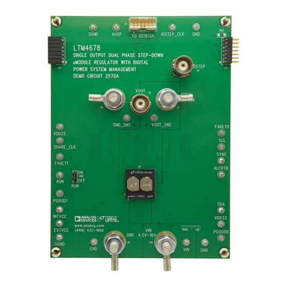
Dual 25A or Single 50A µModule Regulator with
Digital Power System Management,1× LTM4678, 50A
DESCRIPTION
Demonstration circuit 2570A is a dual output, high effi-
ciency, high density, µModule
input range. The output voltage is adjustable from 0.5V
to 33V and it can supply 50A maximum load current. The
demo board has a
LTM
4678
®
a dual 25A or single 50A step-down regulator with digital
power system management. Please see LTM4678 data
sheet for more detailed information.
DC2570A powers up to default settings and produces
power based on configuration resistors without the
need for any serial bus communication. This allows
easy evaluation of the DC/DC converter. To fully explore
the extensive power system management features of the
regulator with 4.5V to 16V
®
µModule regulator, which is
Figure 1. Single-Output 50A LTM4678/DC2570A Demo Circuit
DEMO MANUAL DC2570A
part, download the GUI software LTpowerPlay
PC and use Analog Devices' I
DC1613A to connect to the board. LTpowerPlay allows
the user to reconfigure the part on-the-fly and store the
configuration in EEPROM, view telemetry of voltage, cur-
rent, temperature and fault status.
GUI Download
The software can be downloaded from:
For more details and instructions of LTpowerPlay, please
refer to LTpowerPlay GUI for LTM4678 Quick Start Guide.
Design files for this circuit board are
All registered trademarks and trademarks are the property of their respective owners.
LTM4678
onto your
®
2
C/SMBus/PMBus dongle
LTpowerPlay
available.
Rev. 0
1
Advertisement

Related Manuals for Linear Analog Devices ADI Power DC2570A


Summary of Contents for Linear Analog Devices ADI Power DC2570A
- Page 1 DEMO MANUAL DC2570A LTM4678 Dual 25A or Single 50A µModule Regulator with Digital Power System Management,1× LTM4678, 50A DESCRIPTION Demonstration circuit 2570A is a dual output, high effi- part, download the GUI software LTpowerPlay onto your ® ciency, high density, µModule regulator with 4.5V to 16V PC and use Analog Devices’...
-
Page 2: Performance Summary
DEMO MANUAL DC2570A PERFORMANCE SUMMARY Specifications are at T = 25°C PARAMETER CONDITIONS UNITS Input Voltage Range Output Voltage, V = 4.5V to 16V, I = 0A to 50A Maximum Output Current, I = 4.5V to 16V, V = 0.5V to 3.3V Typical Efficiency = 12V, V = 1.0V, I... - Page 3 DEMO MANUAL DC2570A QUICK START PROCEDURE – LOAD1 0A-50A – DC2570A F02 4.5V TO 16V – – – Figure 2. Proper Measurement Equipment Setup – Figure 3. Measuring Output Voltage Ripple Rev. 0...
- Page 4 DEMO MANUAL DC2570A QUICK START PROCEDURE Connecting a PC to DC2570A set points, OV/UV limits, temperature fault limits, sequencing parameters, the fault log, fault responses, You can use a PC to reconfigure the power management GPIOs and other functionalities. The DC1613A dongle features of the LTM4678 such as: nominal V , margin may be plugged when V...
- Page 5 DEMO MANUAL DC2570A QUICK START PROCEDURE (20MHz BW) [50mV/DIV] 25A TO 37.5A LOAD STEP 100 s/DIV DC2570A F06 Figure 6. Output Voltage V vs Load Current (V = 1.0V) (20MHz BW) [5mV/DIV] 2 s/DIV DC2570A F07 Figure 7. Output Voltage Ripple at V = 12V, V = 1.0V, I = 50A...
- Page 6 DEMO MANUAL DC2570A QUICK START PROCEDURE Figure 8. Thermal at V = 12V, V = 1.0V, I = 45A, T = 25°C, No Airflow Figure 9. Thermal at V = 12V, V = 1.0V, I = 50A, T = 25°C, 200LFM Airflow Rev. 0...
- Page 7 DEMO MANUAL DC2570A LTpowerPlay SOFTWARE GUI LTpowerPlay is a powerful Windows based develop- issues when bringing up rails. LTpowerPlay utilizes the ment environment that supports Analog Devices power DC1613A USB-to-SMBus controller to communicate with system management ICs and μModules, including the one of many potential targets, including the LTM4675, LTM4675, LTM4676, LTM4677, LTM4678, LTC 3880,...
- Page 8 DEMO MANUAL DC2570A LTpowerPlay QUICK START PROCEDURE d. If you want to change the output voltage to a differ- The following procedure describes how to use LTpowerPlay ent value, like 1.5V. In the Config tab, type in 1.5 in to monitor and change the settings of LTM4678. the VOUT_COMMAND box, like this: 1.
-
Page 9: Parts List
DEMO MANUAL DC2570A PARTS LIST ITEM QTY REFERENCE PART DESCRIPTION MANUFACTURER/PART NUMBER Required Circuit Components CIN1 CAP ., 150μF, ALUM POLY HYB, 35V, 20% PANASONIC, EEH-ZA1V151P COUT1, COUT2, COUT3, COUT6, CAP ., 100μF, X5R, 6.3V, 20%,1210 AVX, 12106D107MAT2A COUT7, COUT8 CIN2, CIN3, CIN4, CIN5 CAP ., 10μF, X5R, 35V, 10%, 1210 AVX, 1210DD106KAT2A... - Page 10 DEMO MANUAL DC2570A PARTS LIST ITEM QTY REFERENCE PART DESCRIPTION MANUFACTURER/PART NUMBER Additional Demo Board Circuit Components COUT4, COUT5 CAP ., 70μF, TANT. POSCAP , 4V, 20%, 7343, 10mΩ, TPF , PANASONIC, 4TPF470ML NO SUBS. ALLOWED RES., 30Ω, 1%, 1W, 2512, AEC-Q200 VISHAY, CRCW251230R0FKEG RES., OPTION, 0603 DIODE, OPTION, SOD-323...
-
Page 11: Schematic Diagram
DEMO MANUAL DC2570A SCHEMATIC DIAGRAM Rev. 0... - Page 12 DEMO MANUAL DC2570A SCHEMATIC DIAGRAM Rev. 0...
- Page 13 DEMO MANUAL DC2570A SCHEMATIC DIAGRAM Rev. 0 Information furnished by Analog Devices is believed to be accurate and reliable. However, no responsibility is assumed by Analog Devices for its use, nor for any infringements of patents or other rights of third parties that may result from its use. Specifications subject to change without notice.
- Page 14 DEMO MANUAL DC2570A ESD Caution ESD (electrostatic discharge) sensitive device. Charged devices and circuit boards can discharge without detection. Although this product features patented or proprietary protection circuitry, damage may occur on devices subjected to high energy ESD. Therefore, proper ESD precautions should be taken to avoid performance degradation or loss of functionality. Legal Terms and Conditions By using the evaluation board discussed herein (together with any tools, components documentation or support materials, the “Evaluation Board”), you are agreeing to be bound by the terms and conditions set forth below (“Agreement”) unless you have purchased the Evaluation Board, in which case the Analog Devices Standard Terms and Conditions of Sale shall govern.
Need help?
Do you have a question about the Analog Devices ADI Power DC2570A and is the answer not in the manual?
Questions and answers