Advertisement
Quick Links
2GIG-TAKE-KIT1
HARDWIRE CONVERSION KIT
INSTALL INSTRUCTIONS
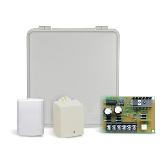
The 2GIG Hardwire Conversion Kit (2GIG‐TAKE‐KIT1) provides installers
with an easy method for taking over a pre‐wired security alarm system
and converting the existing hardwired zones to wireless zones.
To ensure optimal performance with the 2GIG Control Panel, the kit
provides an ABS Plastic enclosure (UL 94: V‐0) to protect the kit's
components. The enclosure houses up to three (3) Super Switch
Takeover Modules (2GIG‐TAKE‐345) and the Power Supply Board with
backup battery charging circuit. It also includes a space for placing a
suitable backup battery.
The kit includes one (1) Super Switch Takeover Module (Wireless
Takeover of an Alarm System. US Patent No. 8,638,218). You can also
install two (2) additional modules, which permits you to convert up to 24
pre‐wired security zones to wireless zones (each module converts eight
(8) zones).
The Super Switch cannot be used to monitor Carbon
IMPORTANT:
Monoxide (CO) or Fire detection zones and the Hardwire
Conversion Kit is intended for indoor use only.
Figure 1 Hardwire Conversion Kit
Box Contents
Verify that the package includes:
• 1—Super Switch Takeover Module (2GIG‐TAKE‐345)
• 1—Plastic Bracket
• 2—Phillips Head Screws for Plastic Bracket
• 1—12/24 VDC Power Supply Board
• 1—16.5VAC 50 VA Grounded Plug‐in Transformer
• 1—ABS Plastic Wall‐Mount Enclosure
• 1—Removable Enclosure Door
• 4—Drywall Anchors and Phillips Head Screws for mounting
the enclosure.
• 1—Double‐sided Adhesive Tape for Super Switch Plastic
Bracket
• 3—2.5 inch (6.35 cm) Double‐Stick Foam Strips for Power
Supply Board
• 1—2.5 inch (6.35 cm) Double‐Stick Foam Strips for Plug‐in
Transformer
Additional Equipment
Additional equipment can be purchased to enhance the Hardwire
Conversion Kit:
• Backup Battery (Required). You must install a 12 V, 1.4 AH
Rechargeable Sealed Lead Acid Battery (or better).
• Linear H208 (Optional). This kit is recommended for locking the
plastic wall‐mount enclosure with a key for additional security.
For details, visit: http://www.linearcorp.com/
product_detail.php?productId=317
Mounting the Enclosure to the Wall
When completing the steps below, refer to Figure 2 "Mounting the
Enclosure to the Wall" on page 2.
To mount the enclosure to the wall:
Choose a location within RF range of the Control Panel. Before you
1
begin, ensure the mounting location is free of electrical wires and
plumbing systems before drilling into the wall.
Temporarily remove the enclosure door by lifting the cover up and
2
pushing it back until the door's hinge pins disengage.
Using the four (4) keyhole slots as a template, mark the location of
3
the four (4) mounting holes at the top of the keyhole slots. Ensure
that the enclosure will be level.
4
Remove the enclosure from the wall and drill 3/16" starter holes for
the screws at the four (4) marked locations.
5
Push each of the wall anchors into the drilled holes, ensuring the
wall anchor heads are flush with the wall.
Screw two (2) of the Phillips head screws into the bottom wall
6
anchors, leaving the heads exposed.
Do not screw these in all the way.
Pull the cord for the Grounded Plug‐in Transformer through one of
7
the access holes or knockout in the back of the enclosure.
8
Pull the wires for all of the wired sensors through the enclosure's
access holes and/or knockout as needed.
9
With the enclosure in place, insert the two (2) screw heads into the
top wall anchors.
Ensure the screw heads are at the upper end of the keyhole slots.
Then tighten both screws.
Lift the enclosure and insert the screw heads into the lower keyhole
10
slots.
Slide the enclosure downwards so the screw heads are at the upper
11
end of the keyhole slots.
Ensure that the enclosure is level.
12
13
Tighten the screws.
14
Continue with "Mounting the Power Supply Board in the Enclosure"
on page 2.
Copyright © 2014 Linear LLC.
1
Advertisement

Related Manuals for Linear 2GIG-TAKE-KIT1


Summary of Contents for Linear 2GIG-TAKE-KIT1
- Page 1 Lift the enclosure and insert the screw heads into the lower keyhole Verify that the package includes: slots. • 1—Super Switch Takeover Module (2GIG‐TAKE‐345) Slide the enclosure downwards so the screw heads are at the upper • 1—Plastic Bracket end of the keyhole slots. • 2—Phillips Head Screws for Plastic Bracket Ensure that the enclosure is level. • 1—12/24 VDC Power Supply Board Tighten the screws. • 1—16.5VAC 50 VA Grounded Plug‐in Transformer Continue with "Mounting the Power Supply Board in the Enclosure" • 1—ABS Plastic Wall‐Mount Enclosure on page 2. • 1—Removable Enclosure Door • 4—Drywall Anchors and Phillips Head Screws for mounting the enclosure. • 1—Double‐sided Adhesive Tape for Super Switch Plastic Bracket • 3—2.5 inch (6.35 cm) Double‐Stick Foam Strips for Power Supply Board • 1—2.5 inch (6.35 cm) Double‐Stick Foam Strips for Plug‐in Transformer Copyright © 2014 Linear LLC.
-
Page 2: Wiring The Components
Hardwire Conversion Kit (2GIG-TAKE-KIT1) | Installation Instructions Figure 2 Mounting the Enclosure to the Wall Mounting the Super Switch in the Enclosure To mount the Super Switch inside the enclosure: Attach the adhesive backing to the back side of the plastic wall bracket for the Super Switch. The adhesive backing is included in the Hardwire Conversion Kit. Affix the plastic wall bracket to the upper‐right corner of the enclosure. See position 3 in Figure 4 Mounting the Super Switch in the Enclosure. If installing more than one (1) Super Switch module, NOTE: mount each plastic wall bracket vertically as shown in Figure 4. The enclosure can house a maximum of three (3) modules. Use the two (2) sheet metal screws (included with the Super Switch) to secure the module to the inside the enclosure. Slide the backplate of the Super Switch downwards over the mounting stubs on the face of the plastic wall bracket. To remove the Super Switch backplate from the plastic wall bracket, slide the backplate in an upwards direction to release it ... - Page 3 Hardwire Conversion Kit (2GIG-TAKE-KIT1) | Installation Instructions Terminals 3‐10 on the super switch correspond to zones 1‐ Connect the plug‐in transformer (included) into an unswitched NOTE: 8. For example, wire the positive (HI) side of zone 1 on the wall outlet. Super Switch to terminal 3. Prepare to secure the transformer to the outlet as follows: • For a standard wall outlet, screw the transformer to the outlet. Repeat the steps above for each additional zone. The screw is included with the plug‐in transformer. Group the LO/(GND) wires together and connect them to terminal 1/G (GND) of the Super Switch. • For a decora wall outlet, affix the double‐sided adhesive tape Replace the front cover on the Super Switch. to the transformer. Then adhere the transformer to the outlet. Ensure the power supply is mounted in the enclosure included with the 2GIG‐TAKE‐KIT1. Figure 6 Connecting Power to the Hardwire Conversion Kit Position the backup battery in the recommended location in the enclosure. Figure 5 Recommended Location for Backup Battery (Not Included) A Wall Outlet...
- Page 4 Hardwire Conversion Kit Wiring Use the diagram below when wiring the Hardwire Conversion Kit. Figure 7 Hardwire Conversion Kit Wiring Diagram Copyright © 2014 Linear LLC.
-
Page 5: Specifications
Hardwire Conversion Kit (2GIG-TAKE-KIT1) | Installation Instructions Installing an Enclosure Door Lock The removable cover on the plastic wall‐mount enclosure is equipped with an knockout that SPECIFICATIONS accepts the Model H208 Lock Kit from Linear LLC. This lets you install an optional key lock. Enclosure To install the optional lock: Material and Certification ABS Plastic UL 94 V‐0 Dimensions 11.5 x 12.5 x 4 in (29.2 x 31.8 x 10.2 cm) Temporarily remove the enclosure door. Takeover Module Locate the knockout for the lock. This is Wireless Signal Range 350 ft, open air, with Wireless Control Panel located in the center at the bottom of the Code Outputs For each of the eight (8) serial zones: Alarm; enclosure door. Restore; Fault; Low Battery Transmitter Frequency 345.00 MHz (crystal controlled) Carefully remove the knockout from the Unique ID Codes Over one (1) million different code enclosure door using a punch tool. combinations Assemble the door lock as described in the H208 Owner’s Manual ... -
Page 6: Limited Warranty
Hardwire Conversion Kit (2GIG-TAKE-KIT1) | Installation Instructions Limited Warranty This Linear LLC product is warranted against defects in material and workmanship for one (1) year. This warranty extends only to wholesale customers who buy direct from Linear LLC or through Linear’s normal distribution channels. Linear LLC does not warrant this product to consumers. Consumers should inquire from their selling dealer as to the nature of the dealer’s warranty, if any. There are no obligations or liabilities on the part of Linear LLC for consequential damages arising out of or in connection with use or performance of this product or other indirect damages with respect to loss of property, revenue, or profit, or cost of removal, installation, or reinstallation. All implied warranties for functionality, are valid only until the warranty expires. This Linear LLC Warranty is in lieu of all other warranties expressed or implied. 2GIG by Linear 1950 Camino Vida Roble, Suite 150 Carlsbad, CA 92008 USA For technical support in the USA and Canada: 855‐2GIG‐TECH (855‐244‐4832) Email: 2gigtechsupport@linearcorp.com Visit web site for technical support hours of operation For technical support outside of the USA and Canada: Contact your regional distributor Visit dealer.2gig.com for a list of distributors in your region PN: 77‐000069‐001 Rev. B Copyright © 2014 Linear LLC.
Need help?
Do you have a question about the 2GIG-TAKE-KIT1 and is the answer not in the manual?
Questions and answers