Bunn OT Operating & Service Manual
Bunn ot: user guide
Hide thumbs
Also See for OT:
- Illustrated parts catalog (47 pages) ,
- Installation & operating manual (35 pages) ,
- Operating & service manual (176 pages)
Table of Contents
Advertisement
BUNN
OPERATING & SERVICE MANUAL
BUNN-O-MATIC CORPORATION
10021.0000G 7/00 © 1989 BUNN-O-MATIC CORPORATION
POST OFFICE BOX 3227
SPRINGFIELD, ILLINOIS 62708-3227
PHONE: (217) 529-6601 FAX: (217) 529-6644
®
OT & RT
G
I N
R N
W A
M ER
W AR
Y
!
AT
DR
HE
ER
AY
G H
NT
S AW
HI
DE
CA
IL
IB LE
S
T BO
ST
SK
NO
M BU
Y RI
Q UI
D
CO
M PL
DO
EP
T LI
RD
KE
CO
E/ HO
ZA
E TO
HA
IL UR
FI RE
IL UR
FA
FA
SS
D
G LA
S AN
RN
BU
Advertisement
Chapters
Table of Contents

Related Manuals for Bunn OT


Summary of Contents for Bunn OT
- Page 1 BUNN OPERATING & SERVICE MANUAL BUNN-O-MATIC CORPORATION PHONE: (217) 529-6601 FAX: (217) 529-6644 10021.0000G 7/00 © 1989 BUNN-O-MATIC CORPORATION ® POST OFFICE BOX 3227 SPRINGFIELD, ILLINOIS 62708-3227 OT & RT M ER W AR S AW IB LE T BO...
-
Page 2: Table Of Contents
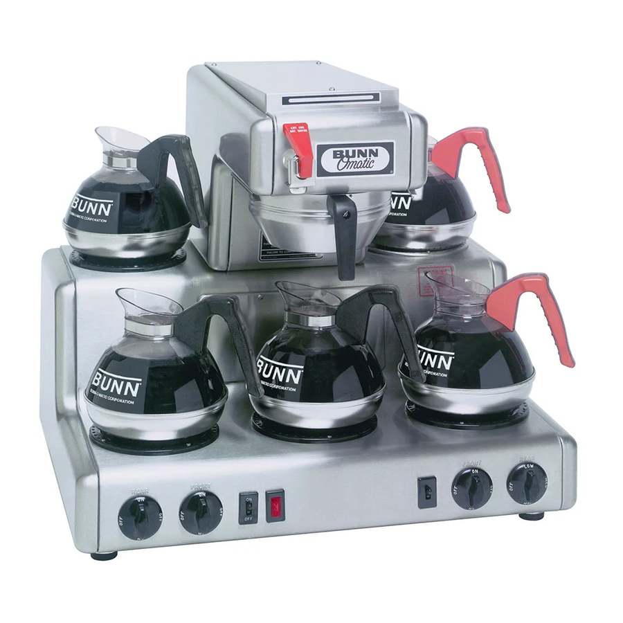
This equipment will brew a half-gallon batch of coffee into an awaiting decanter at the press of a button. The OT has two and the RT has five warmers to keep the beverage at the right temperature, on the RT one of which is capable of heating water to boiling. -
Page 3: User Notices
USER NOTICES Carefully read and follow all notices on the equipment and in this manual. They were written for your protection. All notices on the equipment should be kept in good condition. Replace any unreadable or damaged labels. 00658.0000 00831.0000 WARNING HIGH HEAT WARMER DO NOT BOIL DECANTER DRY... -
Page 4: Electrical Requirements
25 feet from the 1/2" water supply line. A tight coil of copper tubing in the water line will facili- tate moving the brewer to clean the counter top. Bunn- O-Matic does not recommend the use of a saddle valve to install the brewer. -
Page 5: Initial Setup
PLUMBING REQUIREMENTS (Cont.) Plumbing Hook-Up Model OT15 has an attached water strainer, proceed to step 2. Models OT20, OT35, & RT35, proceed as follows: Remove the rear panel and bottom pan. Run the long piece of tubing from the strainer (supplied) under the brewer and attach it to the water inlet fitting on the solenoid. -
Page 6: Adjusting Brew Volumes
3. Setting programming disable feature. If it becomes necessary to prevent anyone from changing brew times once programmed, you can set the SET/LOCK switch to the “LOCK” position. This will prevent any program- ming to be done until switch is once again placed in the “SET” position. OPERATING CONTROLS MODEL OT MODEL RT P1687 P1688... -
Page 7: Coffee Brewing
COFFEE BREWING Start each brew cycle with an empty, clean, half-gallon decanter. Insert a BUNN® filter into the funnel. Pour the fresh coffee into the filter and level the bed of grounds by gently shaking. Slide the funnel into the funnel rails. -
Page 8: Troubleshooting
TROUBLESHOOTING A troubleshooting guide is provided to suggest probable causes and remedies for the most likely problems encountered. If the problem remains after exhausting the troubleshooting steps, contact the Bunn-O-Matic Technical Service Department. • Inspection, testing, and repair of electrical equipment should be performed only by qualified service personnel. - Page 9 TROUBLESHOOTING (cont.) Problem Brew cycle will not start. (cont.) Water flows into tank continuously (On/Off brew station warmer switch "OFF"). Water flows into tank continuously (On/Off brew station warmer switch "ON"). Water is not hot. Decanter warmer is not hot. Probable Cause 4.
- Page 10 TROUBLESHOOTING (cont.) Problem Spitting or unusual steaming from sprayhead. Inconsistent beverage level in de- canter. Consistently high or low beverage level in decanter. Dripping from sprayhead. Probable Cause 1. Control Thermostat 2. Lime build-up CAUTION: Tank and tank compo- nents should be delimed regularly depending on local water conditions.
- Page 11 Page 11 Remedy The brew cycle should be started only with an empty decanter under the funnel. BUNN® paper filters should be used for proper extraction. A sufficient quantity of fine or drip grind coffee should be used for proper extraction.
-
Page 12: Service
Access is gained by removing the top lid, FIG. 1 attached with three #8-32 slotted head screws. On the model OT, the upper warmer, switch, and associated indicator lamp are located on this re- movable top lid. -
Page 13: Brew Timer (Early Models)
SERVICE (cont.) Brew Timer (Early Models) FIG. 2 BREW TIMER Location: The brew timer is located behind the front panel to the right of the tank, FIG. 2. Test Procedure: Disconnect the brewer from the power source and separate the polarized, three-pin connectors between the timer and brewer wiring harness and rotate the brew timer dial fully counterclockwise. -
Page 14: Digital Timer (Late Models)
SERVICE (cont.) DIGITAL BREW TIMER (Late Models) FIG. 4 DIGITAL BREW TIMER Location: The timers are located inside the front of the trunk on the upper right side of the component brackets. Test Procedure. NOTE: Do not remove or install wires while timer board is installed. - Page 15 SERVICE (cont.) DIGITAL BREW TIMER (Late Models)(cont.) 3. Remove all wires from the timer. 4. Attach all wires to the replacement timer board prior to installation to the component mounting bracket. Refer to FIG. 5 when reconnecting the wires. 5. Install new circuit board with spacers (as re- quired) to the component mounting bracket.
-
Page 16: Control Thermostat
SERVICE (cont.) Control Thermostat FIG. 6 CONTROL THERMOSTAT Location: The control thermostat is located behind the front panel, FIG. 6 to the left of the tank. To test the control thermostat, access will also be needed to the tank heater located in the top of the brewer. -
Page 17: Warmer(S)
S AN FIG. 9 WARMERS Location: OT: One of the warmers is beneath the brew funnel and the other is on the top lid, FIG. 8. RT: These warmers include the one beneath the brew funnel, the ones on the right and left of the brew station, and the one above and to the left of the brew station as viewed from the front, FIG. -
Page 18: Rt: Right Rear Three Heat
SERVICE (cont.) Warmer RT: Right Rear Three Heat IN G H HE T BO T LIQ E HA S FA D FIR S AN FIG. 11 THREE HEAT WARMER Location: The three heat warmer is above and to the right of the brew station as viewed from the front, FIG. -
Page 19: Ot: On/Off Brew Station & Upper
Push the new switch firmly into the opening. FIG. 15 WARMER SWITCH WIRING P1688 MODEL OT Upper BLK A BLK B OT On/Off Brew Station BLK A BLK B RT On/Off Brew Station BLK A BLK B Page 19 BLK (A) (see below) -
Page 20: Rt: Left Rear, Left Front, & Right Front Rotary
SERVICE (cont.) Warmer Switch(es) RT: Left Rear, Left Front, & Right Front H HE T BO T LIQ E HA S FA D FIR S AN FIG. 16 WARMER SWITCHES Location: These warmer switches are the two at the left and the left most one on the right of the base as viewed from the front, FIG. -
Page 21: Rt: Right Rear Three Heat Rotary
SERVICE (cont.) Warmer Switch(es) Right Rear Three Heat Rotary S AW T BO E HA S FA S AN FIG. 18 THREE HEAT WARMER SWITCH Location: This switch is the farthest on the right of the base as viewed from the front, FIG. 18. Its knob is marked Off/Low/Med/High. -
Page 22: Indicator Lamp(S)
SERVICE (cont.) Indicator Lamp(s) FIG. 20 INDICATOR LAMP - MODEL OT IN G H HE T BO T LIQ E HA S FA D FIR S AN FIG. 21 INDICATOR LAMP - MODEL RT Location: The indicator lamps are located beneath their associ- ated warmers, FIG.s 20 and 21. -
Page 23: Limit Thermostat
SERVICE (cont.) Limit Thermostat FIG. 23 LIMIT THERMOSTAT Location: The limit thermostat is located on the tank lid between the tank heater terminals, FIG. 23. Test Procedure: Disconnect the brewer from the power source. Check voltage across the black wire from the limit thermostat and the white or red wire on the tank heater terminal. -
Page 24: Solenoid Valve
SERVICE (cont.) Solenoid Valve P1699 FIG. 25 SOLENOID VALVE Location: The solenoid valve is located below and to the left of the tank as viewed from the rear, FIG. 25. Test Procedure: Check the voltage across the white and black wires with a voltmeter when the On/Off brew sta- tion warmer switch is in the upper position and the start switch is pressed to the lower position... -
Page 25: Start Switch
SERVICE (cont.) Start Switch FIG. 27 START SWITCH - MODEL OT H HE T BO T LIQ E HA S FA D FIR S AN FIG. 28 START SWITCH - MODEL RT Location: The start switch is located in the base, below and to the right of the brew station, FIG.s 27 &... -
Page 26: Wiring Diagrams
SERVICE (cont.) Tank Heater FIG. 30 TANK HEATER Location: The tank heater is located on the tank lid, FIG. 30. Test Procedure: Check the voltage across the black and white or red wires on the tank heater with a voltmeter when the control thermostat is turned "ON"... -
Page 27: Thermal Cut-Off
SERVICE (cont.) Thermal Cut-off Location: The thermal cut-off is located on the tank heater, FIG. FIG. 32 THERMAL CUT-OFF Test Procedures: Disconnect the brewer from the power source. Disconnect the thermal cut-off from the tank heater terminal and the wiring harness. Check for continuity across the thermal cut-off terminals using an ohmmeter. -
Page 28: Wiring Schematics
SCHEMATIC WIRING DIAGRAM OT SW. & LIMIT THERMOSTAT THERMOSTAT P1, P2, & P3 ARE PINS OF A POLARIZED THREE-PIN CONNECTOR. 120 VOLTS AC 2 WIRE 120/240 VOLTS AC 3 WIRE SINGLE PHASE 60 HZ (FAUCET OPTION ONLY) THERMAL CUT-OFF TANK HEATER "KEEP WARM"... - Page 29 3500W TANK HEATER "KEEP WARM" HEATER 130W UPPER WARMER 130W BREW STATION WARMER BLU/BLK WHI/BLU BREW TIMER 10280.0000D 7/00 © 1988 BUNN-O-MATIC CORPORATION Page 29 GREEN WHI/GRN P1, P2, & P3 ARE PINS OF A POLARIZED THREE-PIN CONNECTOR. GRINDER INTERFACE...
- Page 30 SCHEMATIC WIRING DIAGRAM OTA LIMIT THERMOSTAT 240 VOLTS AC 2 WIRE SINGLE PHASE 50-60 HZ 10282.0000B 7/00 © 1988 BUNN-O-MATIC CORPORATION SW. & THERMOSTAT TANK HEATER RED/BLK RED/BLK UPPER WARMER BREW STATION WARMER BLU/BLK WHI/BLU WHI/GRN BREW TIMER Page 30...
- Page 31 SCHEMATIC WIRING DIAGRAM OT25B LIMIT THERMOSTAT 100 VOLTS AC 2 WIRE SINGLE PHASE 50-60 HZ 10635.0000B 7/00 © 1991 Bunn-O-Matic Corporation READY INDICATOR SW. & THERMOSTAT TANK HEATER UPPER WARMER BREW STATION WARMER BLU/BLK WHI/BLU WHI/GRN BREW TIMER Page 31 GRN/YEL P1, P2, &...
- Page 32 SCHEMATIC WIRING DIAGRAM OT35B LIMIT THERMOSTAT 200 VOLTS AC 2 WIRE SINGLE PHASE 50-60 HZ 10637.0000B 7/00 © 1991 Bunn-O-Matic Corporation READY INDICATOR SW. & THERMOSTAT TANK HEATER UPPER WARMER BREW STATION WARMER BLU/BLK WHI/BLU BREW TIMER Page 32 GRN/YEL P1, P2, &...
- Page 33 THERMOSTAT P1, P2, & P3 ARE PINS OF A POLARIZED THREE-PIN CONNECTOR. 120/240 VOLTS AC 3 WIRE SINGLE PHASE 60 HZ 10277.0000D 7/00 © 1988 BUNN-O-MATIC CORPORATION (FAUCET OPTION ONLY) SW. & THERMAL CUT-OFF THERMOSTAT "KEEP WARM" HEATER WARMER BLU/BLK...
- Page 34 SCHEMATIC WIRING DIAGRAM RTA LIMIT THERMOSTAT 240 VOLTS AC 2 WIRE SINGLE PHASE 50-60 HZ 10283.0000C 7/00 © 1988 BUNN-O-MATIC CORPORATION SW. & THERMOSTAT TANK HEATER WARMER BLU/BLK WHI/BLU WHI/GRN BREW TIMER LEFT REAR WARMER LEFT FRONT WARMER RIGHT FRONT WARMER...
- Page 35 SCHEMATIC WIRING DIAGRAM RT25B LIMIT SW. & THERMOSTAT THERMOSTAT 100 VOLTS AC 2 WIRE SINGLE PHASE 50-60 HZ 10634.0000D 7/00 © 1991 Bunn-O-Matic Corporation READY INDICATOR TANK HEATER WARMER BLU/BLK WHI/BLU WHI/GRN BREW TIMER LEFT REAR WARMER LEFT FRONT WARMER...
- Page 36 SCHEMATIC WIRING DIAGRAM RT35B LIMIT SW. & THERMOSTAT THERMOSTAT 200 VOLTS AC 2 WIRE SINGLE PHASE 50-60 HZ 10636.0000D 7/00 © 1991 Bunn-O-Matic Corporation READY INDICATOR TANK HEATER WARMER BLU/BLK WHI/BLU WHI/GRN BREW TIMER LEFT REAR WARMER LEFT FRONT WARMER...
Need help?
Do you have a question about the OT and is the answer not in the manual?
Questions and answers