Table of Contents
Advertisement
Quick Links
Advertisement
Table of Contents

Subscribe to Our Youtube Channel
Related Manuals for Bindicator VRF II Series


Summary of Contents for Bindicator VRF II Series
- Page 1 II Series ® Installation & Operation Manual...
-
Page 3: Table Of Contents
VRF II Series Integral Model Only VRF II Series Remote Model Only Figure 3. VRF II Series - Integral Enclosure with Cover Removed - STANDARD Figure 4. VRF II Series - Integral Enclosure with Cover Removed - ADVANCED Figure 5. Power and Ground Connections Figure 6. - Page 4 VI. SET-UP ............................13 Operation Product Overview - STANDARD Figure 11. Switch Functions Product Overview - ADVANCED Figure 12. Switch Functions Pro-Guard ® Fail-Safe Selection Time Delay Settings - STANDARD Time Delay Settings - ADVANCED Sensitivity Settings - STANDARD Sensitivity Settings - ADVANCED Calibration - Automatic Calibration - Manual - ADVANCED ONLY Calibration - Test - ADVANCED ONLY...
-
Page 5: Handling & Storage
II Series ® Installation & Operation Manual I. HANDLING AND STORAGE SAVE THESE INSTRUCTIONS INSPECTION AND HANDLING Do not dispose of the carton or packing materials. Each package should be inspected upon receipt for damage that may have occurred due to mishandling during shipping. -
Page 6: General Safety
II. GENERAL SAFETY AUTHORIZED PERSONNEL All instructions described in the document must be performed by authorized and qualified service personnel only. Before installing the unit, please read these instructions and familiarize yourself with the requirements and functions of the device. The required personal protective equipment must always be worn when servicing this device. -
Page 7: Product Description
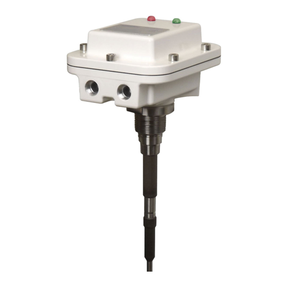
Material coming in contact with the unit’s probe causes its output relay to change state, thereby indicating the presence of material. Operation of the VRF II Series is based upon the Bindicator Opti-Sense™ technology to measure changes ®... -
Page 8: Technical Specifications
TECHNICAL SPECIFICATIONS FUNCTIONAL Power Requirements Universal (± 10%), 120-240 VAC 50/60 Hz or 24-48 VDC Power Consumption - STANDARD 10 W AC; 3 W DC Power Consumption - ADVANCED 11 W AC; 4 W DC Fuse Slow Blow, 1A 300 V (Not User Serviceable) -
Page 9: Mechanical Installation
MOUNTING CONSIDERATIONS The VRF II Series must be located at the position where level indication is desired. The probes may be mounted through the top or side wall of the vessel. To ensure reliable operation, observe the following guidelines when choosing the mounting location. -
Page 10: Electrical Installation
cations). • Do not allow moisture to enter the electronics enclosure. Conduit should slope downward from the VRF II Series housing. Install drip loops and seal conduit with silicone rubber product. DISCONNECT REQUIREMENTS FOR PERMANENTLY INSTALLED EQUIPMENT A dedicated disconnecting device (circuit breaker) must be provided for the proper installation of the unit. If independent circuits are used for power input and main relay outputs, individual disconnects are required. -
Page 11: Protective Earth Ground
ELECTRICAL CONNECTIONS Note: The VRF II Series can be operated from 120-240 VAC 50/60 Hz or 24-48 VDC and provides reverse polarity protection in the event of a wiring error. VRF II SERIES INTEGRAL MODEL ONLY Input Power Connections 1. -
Page 12: Vrf Ii Series Remote Model Only
Note: The VRF II Series incorporates pluggable terminal blocks for ease of connection. If the terminal block is unplugged while making connections, ensure it is seated properly when reinstalled. 5. Attach power leads to terminal block as shown in Figure 5. - Page 13 Main Relay Connections 8. Refer to Figure 3 or 4 and 6 when connecting to the main relay. 9. Pull approximately 9” (23 cm) of cable through conduit and strip ” (6 to 7 mm). 10. Attach leads to terminal block as shown in Figure 3 or 4.
- Page 14 Figure 3. VRF II Series: Integral Enclosure with Cover Removed - STANDARD Power LED Dip Switch SW1 Alarm LED To Earth Ground Note 1 Power & Ground Connections Main Relay Connections Notes: 1) For Safety and to insure Proper Operation, Attach Ground Wire to an Adequate Earth Ground.
- Page 15 Figure 6. Main Relay Connections Power & Ground Connections PRIMARY GROUND Figure 7. Auxiliary Relay Connections - ADVANCED ONLY Figure 8. VRF II Series Remote Enclosure with Cover Removed - STANDARD To Earth Ground Note 1 Dip Switch SW1 Remote Connection...
- Page 16 Figure 9. VRF II Series Remote Enclosure with Cover Removed - ADVANCED Alarm LED Power LED To Earth Ground Note 1 Remote Connection Diagram Dip Switch Power & Ground Connections Main Relay Auxillary Relay Connections Connections Cal Button Notes: 1) For Safety and to insure Proper Operation, Attach Ground Wire to an Adequate Earth Ground.
-
Page 17: Set-Up
ADJUSTMENTS. OPERATION The VRF II Series will begin operating and the green Power LED will be illuminated when power is applied. Once properly installed, the VRF II Series should be calibrated (refer to Calibration Section) when material is below the probe. The status of the red Alarm LED is determined by the selected fail-safe mode and whether or not the probe is in material. Refer to Fail-Safe Operation section. If the unit is calibrated prior to its final installation or if it... -
Page 18: Product Overview - Advanced
Figures 3 and 8 show the electronics of the integral and remote versions of the VRF II Series respectively. The figures show the location of the electrical connections, dip switches SW5, two rotary switches SW3 and 4, and the Power and Alarm LEDs. The settings of the VRF II Series are controlled by SW3 through 5 as shown in Figure 12. -
Page 19: Fail-Safe Selection
FAIL-SAFE SELECTION The VRF II Series models are factory set for high level fail-safe operation. The Fail-Safe is controlled by SW1, position 5. HIGH LEVEL FAIL-SAFE OPERATION (DEFAULT) DIP Switch HIGH LEVEL FAIL-SAFE • STANDARD: SW1-5 is OFF Level BELOW Probe • ADVANCED: SW5-1 is OFF... -
Page 20: Time Delay Settings - Standard
TIME DELAY SETTINGS - STANDARD This setting will delay the time between when the VRF II Series senses material and the main relay changes state. The delay is only in this direction, regardless of fail-safe setting. There is no added delay when the material leaves the probe. There is a fixed internal delay when material leaves the probe and this delay varies... -
Page 21: Sensitivity Settings - Standard
SENSITIVITY SETTINGS - STANDARD There are four different sensitivity ranges on the VRF II Series that can be selected using SW1 Position 1 and 2. The unit is factory set to 2 pf sensitivity. SW1 Position 1 SW1 Position 2... - Page 22 TEST - ADVANCED ONLY The VRF II Series provides a means for self-test using the magnetic FOB provided with the unit. When the unit is not in alarm, place and hold the FOB over the “TEST” label on the cover. If the unit is functioning properly, the unit will alarm according to the selected fail-safe mode as shown below.
-
Page 23: Maintenance
VII. MAINTENANCE PREVENTATIVE MAINTENANCE No scheduled preventative maintenance is required for the VRF II Series units when properly applied and installed correctly. There is no cleaning required for the unit before or during installation. If the cover is removed after the unit has been in service, it is recommended to replace the gasket to prevent the ingress of water or dust. -
Page 24: Dimensional Drawings
IX. DIMENSIONAL DRAWINGS VRF180913 Rev. A... - Page 25 VRF180913 Rev. A...
- Page 26 VRF180913 Rev. A...
- Page 27 VRF180913 Rev. A...
- Page 28 VRF180913 Rev. A...
- Page 29 VRF180913 Rev. A...
- Page 30 Notes VRF180913 Rev. A...
- Page 31 Notes VRF180913 Rev. A...
- Page 32 150 Venture Boulevard Spartanburg, SC 29306 Tel: (800) 778-9242 2013 All rights reserved. Fax: (864) 574-8063 All data subject to change without notice. sales@bindicator.com www.bindicator.com VRF180913 Rev. A...
Need help?
Do you have a question about the VRF II Series and is the answer not in the manual?
Questions and answers