
Subscribe to Our Youtube Channel
Related Manuals for Bindicator TDR-1000


Summary of Contents for Bindicator TDR-1000
- Page 1 ® TDR180002 Rev. B TDR-1000 GUIDED WAVE RADAR Quick Start Guide INSTALLATION, OPERATION & MAINTENANCE MANUAL...
- Page 2 If any questions or problems arise during ® the installation, please contact Bindicator Applications at 1-800-778-9242. The TDR-1000 model must only be installed and operated as described in this operating ® instruction. Please note that other action can cause damage for which Bindicator does not take responsibility.
-
Page 3: Table Of Contents
TABLE OF CONTENTS 1.0 Range of Use 2.0 Description 3.0 Measured Variable (distance, level, volume) Measuring Range 4.0 Mounting Excessive Bending of the Cable Mounting on a Nozzle Interference between two TDR's 5.0 Electrical Connection 6.0 Technical Specifications 7.0 Programmed Information... -
Page 4: Range Of Use
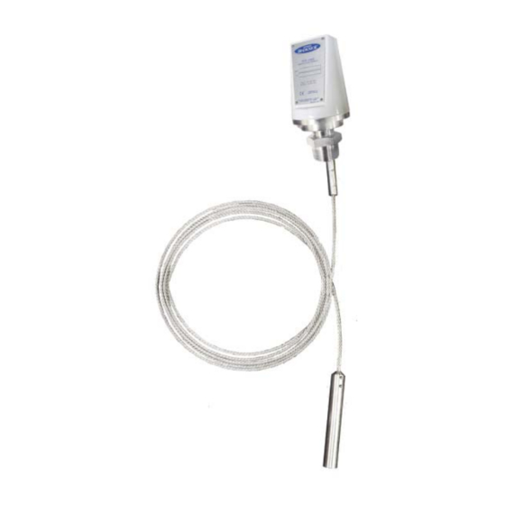
1.0 RANGE OF USE The TDR-1000 level gauging system is a 2 wire transmitter, designed to measure the distance, level and volume of liquids, slurries, solids and particulate materials. It can be operated on storage and process tanks. 2.0 Description The measuring system consists of the sensor and the signal converter. -
Page 5: Excessive Bending Of The Cable
Avoid nozzle size higher than 5.9", especially when B < 3.1". Try to ensure A does not exceed B. 4.3 Interference between two TDR-1000 There must be at least 6.5ft between devices if installed in the same vessel. 6.5 ft ®... -
Page 6: Electrical Connection
The electrical connection for the power supply is made in the terminal compartment of the signal converter - 18-35VDC. In case of installation in hazardous areas, only certified intrinsically safe equipment may be connected to the TDR-1000. 1. Connector: 3 poles + ground. Wire cross-section max 0.059m (1.5 mm... -
Page 7: Technical Specifications
Electrical Signal Output Two wire Electrical Connection: 18 to 35 VDC Power Supply: 4/20mA Current Output: Environment -22° to 131°F Ambient Temperature: Protection Category to IP66, Nema 4X EN 60529 / IEC 529: ® BINDICATOR Installation, Operation & Maintenance Manual... -
Page 8: Programmed Information
7.0 Programmed Information CHECK LIST PARAMETERS TDR-1000 to:________________________________ Date:______________ Device No. ________________________________ Comm. No.__________________________________ Location_______________________________________________________________________________ Contact person _____________________________ Telephone__________________________________ Remarks: ______________________________________________________________________________ _______________________________________________________________________________________ Menu item_________________________________ Changed on__________________________________ Fct. Configuration parameters (customer) 1.1.1 Tank height 1.1.2 Dead zone 1.1.3 Time constant 1.1.6 Probe length 1.2.4 Length unit... - Page 9 Notes ® BINDICATOR Installation, Operation & Maintenance Manual...
- Page 10 ® 150 VENTURE BOULEVARD SPARTANBURG, SC 29306 PHONE: 864.574.8060, FAX: 864.574.8063 CUSTOMER CARE: 800.778.9242 WWW.BINDICATOR.COM SALES@BINDICATOR.COM 2007 ALL RIGHTS RESERVED ALL DATA SUBJECT TO CHANGE TDR180002 Rev.B...
Need help?
Do you have a question about the TDR-1000 and is the answer not in the manual?
Questions and answers