Table of Contents
Advertisement
Quick Links
OWNER'S MANUAL
115-230 Volt/50Hz/1 Phase
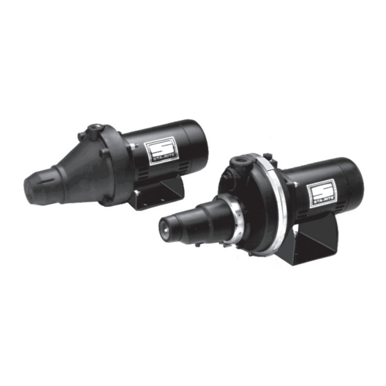
Corrosion Resistant
Shallow Well Jet Pump
MODELS
1/3 HP
1/2 HP
3/4 HP
1 HP
5PNB
5PNC
5PLSWD
5PLSWE
5PNB-MK
5PNC-MK
5PLSWD-MK6
5PLSWE3
293 WRIGHT STREET, DELAVAN, WI 53115 WWW.STA-RITE.COM
PH: 888-782-7483
S193 (11/05/12)
© 2012 Pentair, Inc. All Rights Reserved.
Advertisement
Table of Contents

Subscribe to Our Youtube Channel
Related Manuals for Pentair Sta-Rite 1/3 HP


Summary of Contents for Pentair Sta-Rite 1/3 HP
- Page 1 Corrosion Resistant Shallow Well Jet Pump MODELS 1/3 HP 1/2 HP 3/4 HP 1 HP 5PNB 5PNC 5PLSWD 5PLSWE 5PNB-MK 5PNC-MK 5PLSWD-MK6 5PLSWE3 293 WRIGHT STREET, DELAVAN, WI 53115 WWW.STA-RITE.COM PH: 888-782-7483 S193 (11/05/12) © 2012 Pentair, Inc. All Rights Reserved.
-
Page 2: Table Of Contents
Corrosion resistant Capacitor voltage may be hazardous. To dis- shallow well jet pump charge motor capacitor, hold insulated handle screwdriver BY THE Domestic well installations with suction lifts of 25’ or less. HANDLE and short capacitor terminals together. Do not touch metal screwdriver blade or capacitor terminals. -
Page 3: Before You Install Your Pump
Before You Install Your PumP PumP/PIPIng InstallatIon pump installation pre-installation NOTICE: Use PTFE pipe thread sealant tape supplied with pump 1. A pump cannot pump air. Make sure that suction pipe has for making all threaded connections to pump itself. Do not use no air leaks. -
Page 4: Well Piping
stanDarD tanK ConneCtion Priming plug (fiG. 4 ) When standard tank is used, air volume control (AVC) adds air to the tank when needed. To connect AVC to pump, remove 1/8” pipe Priming tee plug from pump body near suction port (Fig. 4). Thread 1/8” com- pression fitting into tapped hole. -
Page 5: Electrical
laKe installation wirinG (fiG. 8) (fiG. 9) 1. Install, ground, wire and maintain pump in accordance with your Same as cased well except as follows: local electrical code and all other codes/ordinances that apply. 1. Protect end of suction pipe, foot valve and strainer with screening. Consult your local building inspector for local code information. -
Page 6: Operation
oPeratIon 3. If, after priming pump several times, no water is pumped, make sure that: priminG the pump (fiG. 10) a. Suction pipe end is in water. b. Suction pipe has no air leaks. Do not run pump with discharge shut off. Pump c. - Page 7 7. Install new “O” Ring gasket on seal plate (Key No. 4, Page 11). 8. Pick up small amount of liquid soap on finger; spread evenly over installinG new seal “O” Ring gasket for lubrication during reassembly. Be careful not to 1.
- Page 8 2. Replace copper insert: 2. Reassembly of pump. A. Clean off all surplus Permatex from around insert cavity. Be A. Clean “O” rings and “O” ring grooves. careful not to scratch or mark the machined bore. It is important B. Lubricate “O” rings with petroleum jelly, and place in that this area be clean so no old Permatex lodges behind the grooves.
-
Page 9: Helpful Hints
CleaninG impeller 1. Follow steps 1A through 1E under “Disassembly and Assembly of Pump” on Page 8. 2. Remove diffuser and impeller from pump per instructions “Removing Motor for Service and Replacing Shaft Seal”, Page 8. 3. Clean impeller and reassemble impeller and diffuser per instruc- tions under “Removing Motor for Service and Replacing Shaft Seal”... -
Page 10: Troubleshooting Chart
troubleshootinG Chart SYMPTOM POSSIBLE CAUSE(S) CORRECTIVE ACTION Motor will not run Disconnect switch is off Be sure switch is on Fuse is blown or circuit has been tripped Replace fuse or reset circuit breaker Starting switch is defective DISCONNECT POWER; Replace starting switch Wires at motor are loose, Refer to instructions on wiring. -
Page 11: Parts
892 0494 repair parts list Model and Horsepower 5PNB 5PNC 5PNB-MK 5PNC-MK Part Description Qty. 1/3 HP 1/2 HP Motor – 115/230V/50Hz/1Phase J218-573 J218-573 Motor, -MK – 220V/50Hz/1Phase J218-976 J218-976A Water Slinger 17351-0009 17351-0009 Seal Plate Assembly (Incl. #5) N103-12P N103-12P “O”... - Page 12 4478 0104 repair parts list Model No. 5PLSWD 5PLSWE Part Description Qty. 5PLSWD-MK 5PLSWE3 Motor - 115/230V/50Hz/1 Phase J218-574A JW218-575A Motor - MK - 220V/50Hz/1 Phase J218-977A – Motor, 5PLSWE3 - 208-220/380-415V/50Hz/3 Phase – J218-816A Water Slinger 17351-0009 17351-0009 Reducer Bushing - 1/2” x 1/8” NPT U78-107PT U78-107PT Pipe Plug - 1/8”...
Need help?
Do you have a question about the Sta-Rite 1/3 HP and is the answer not in the manual?
Questions and answers