Table of Contents

Subscribe to Our Youtube Channel
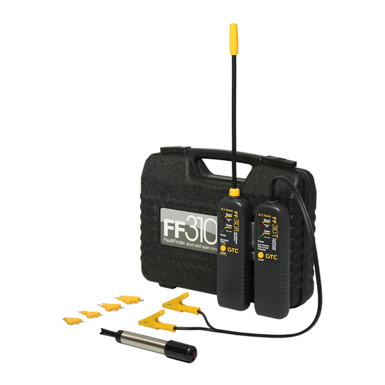
Summary of Contents for GTC FaultFinder FF310
- Page 1 Instruction Manual Manuel d’instructions Short / Open Circuit Finder Current Drain & Circuit Tracer Détecteur de courts-circuits ou de circuits ouverts Détecteur de perte de courant et de circuit...
- Page 2 CAUTION VERY IMPORTANT : Read this first • For use only with DC voltage. Do not connect to circuits exceeding 42 volts DC under any circumstances. • DO NOT USE on AC voltage. • Do not use on any circuit directly or indirectly connected to AC lines or any other AC power source. •...
- Page 3 Procedure to select the tracer range 1. Unit should be on, if not, turn it on by momentarily pressing the On/Off button. 2. Press and hold On/Off button for approximately 3 seconds until a beeping and flashing following the pattern below indicates that the desired sensitivity level is set: a) Low sensitivity: a single (1) flash and beep.
-
Page 4: Locating Short Circuits
LOCATING SHORT CIRCUITS Refer to the hook-up reference chart. 1. Observe the limits and safety precautions at all times. 2. Connect the transmitter in series with the short-circuited wire, making sure one of the unit’s clips is connected to the circuit’s positive supply (or vice versa for vehicles with positive supply connected to chassis). -
Page 5: Locating Current Leaks
LOCATING CURRENT LEAKS Hook up and procedures for locating current leaks are essentially the same as for locating short circuits. The transmitter sees the leak as a weak short circuit or connection to ground. For locating a current leak simply follow the wire with positive (beeping and flashing) audio/visual indicator’s feedback on the tracer, from source to leak location (short circuit). -
Page 6: Hook Up Reference Chart
HOOK UP REFERENCE CHART Fig. 1 - Set Up for tracing short or open circuits or location of wiring TRANSMITTER TRACER Fig. 2 - Set Up for tracing short or open circuits, or locating Battery of wiring TRACER TRANSMITTER Fuse Socket or Connector Fig. - Page 7 GENERAL PROCEDURES AND SPECIAL CASES How to position the probe relative to the wires Fig. 5 - Probe positioning For the best possible range the tracer’s probe should be positioned perpendicular (at 90°) to the wire and either above or below it, as shown in figure 5 below Probe Probe Wire...
- Page 8 From time to time the batteries on both units will need to be replaced. When you notice a dimming indicator light and a diminishing level of audio output, the batteries should be replaced with a new set of 9-Volt alkaline batteries. To install the new batteries, replace the ones in the units for the new batteries observing the polarity.
-
Page 9: Technical Specifications
TECHNICAL SPECIFICATIONS Transmitter: Voltage range: 6 to 42 Volts Indicator: Green LED indicator for Power On/Open circuits Red LED indicator for short circuits Power source: 9 Volt alkaline battery. Type Duracell MN 1604 or equivalent Connector: Two universal micro-clips with auto polarity features and 12” long cable Battery life: Approximately. -
Page 10: Avant De Commencer
ATTENTION TRÈS IMPORTANT : lire ce qui suit en premier • Utiliser avec courant continu (DC) seulement. Ne pas brancher sur un circuit dépassant 42 volts de courant continu (DC) en aucune circonstance. • Ne pas utiliser avec courant alternatif (AC) •... - Page 11 • Procédure de sélection : 1. L’appareil doit être en fonction, s’il ne l’est pas appuyer sur le bouton “On/Off”. 2. Appuyer à nouveau sur le bouton “On/Off” et le maintenir approximativement 3 secondes jusqu’à l’obtention d’un signal sonore et d’un signal clignotant. a) Basse sensibilité...
- Page 12 LOCALISER LES COURTS-CIRCUITS Pour référence, consulter le tableau de raccordement. 1. Observer les limites de l’appareil et suivre les mesures de sécurité en tout temps. 2. Connecter le transmetteur en série avec le fil court-circuité, une des pinces du transmetteur doit être branchée à...
- Page 13 LOCALISER LES DISPERSIONS DE COURANT Le raccordement et les procédures à suivre pour localiser les dispersions de courant sont essentiellement les mêmes que pour localiser les courts-circuits. Le transmetteur perçoit la dispersion comme un court- circuit faible ou un raccordement à la terre. Pour localiser une dispersion de courant, il faut suivre le fil de la source à...
- Page 14 TABLEAU DES RACCORDEMENTS Fig. 1 - Pour localiser un fil, un court-circuit ou un circuit ouvert. TRANSMETTEUR DÉTECTEUR Fig. 2 - Pour localiser un fil, un court-circuit ou un circuit ouvert. Batterie DÉTECTEUR TRANSMETTEUR Prise pour fusible ou connecteur Fig. 3 - Pour localiser un court-circuit ou identifier un fil.
- Page 15 IDENTIFICATION DU FIL Se référer au tableau des raccordements Les fils peuvent être identifiés en suivant le raccordement et les procédures pour “Localiser les courts- circuits” ou “Localiser les circuits ouverts” selon la configuration particulière du circuit. Pour identifier les fils avec charge connectée : connecter le transmetteur au circuit à être identifié, tel qu’indiqué...
- Page 16 Faisceaux et canalisation - cas spéciaux Fig. 6 - Mise sous tension et hors tension du “Déceleur de fuites” Une attention toute particulière doit être apportée lors de la détection d’un fil divisé, situé à l’intérieur d’un faisceau ou d’une canalisation. Il peut être possible de suivre le mauvais embranchement sur une courte distance et de recevoir un signal sonore et un signal visuel, car la sonde peut percevoir le signal de l’autre embranchement situé...
-
Page 17: Spécifications Techniques
SPÉCIFICATIONS TECHNIQUES Transmetteur Voltage : 6 à 42 volts Indicateur : Indicateur à iode vert pour mise sous tension et circuit ouvert Indicateur à iode rouge pour court-circuit Source d’énergie : Pile 9 Volt alcaline - Duracell MN1604 ou l’équivalent Connecteur : Deux mini-pinces universelles à... - Page 18 Part # FF310MN1702EF © 1996-2017 General Technologies Corp. Printed in Canada...


Need help?
Do you have a question about the FaultFinder FF310 and is the answer not in the manual?
Questions and answers