Table of Contents
Advertisement
Advertisement
Table of Contents

Subscribe to Our Youtube Channel
Related Manuals for GTC FF310


Summary of Contents for GTC FF310
- Page 1 User’s Manual for electrical and electronic circuits...
-
Page 2: Table Of Contents
Exceeding the limits listed above when using this apparatus, or not observing the precautions listed above can expose you to physical injury and permanently damage your instrument and parts and components of the vehicle under test. “V Ready” and “GTC” are registered trademarks of General Technologies Corp. -
Page 3: Check Out List
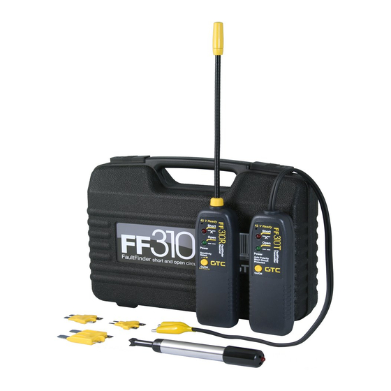
1 - Check out list The FF310 FaultFinder set consists of: FF310R - Receiver FF310T - Transmitter CT8002AA Professional Circuit Tester CT6100 Fuse Socket Connectors 2 factory supplied 9 volt alkaline batteries, type Duracell MN1604 ... -
Page 4: Setting The Sensitivity Level
4 - Setting the sensitivity level The FF310R has three user selectable sensitivity ranges: ‘Low’, ‘Medium’ and ‘High’. These ranges allow the technician to choose the degree of sensitivity most suitable to the particular detection being performed. 4.1 Checking the current sensitivity setting: The FF310R’s current sensitivity setting is displayed when the On/Off button is pressed for 2 or 3 seconds while the unit is ‘ON’... -
Page 5: How To Use The Sensor
5 - How to use the sensor: The probe of the FF310R is built of coiled steel equipped with a sensor (yellow cylinder), and can be bent as needed, in order to reach wires in congested or difficult areas. Depending on the circuit characteristics and the sensitivity setting, the probe’s sensor will pick-up the signal from the wire in a wide range of positions . -
Page 6: Wire Tracing
6.10 The short circuit is located in the area where the audio/visual signal stops or changes signifi cantly. 6.11 When the test is completed, switch off the FF310T unit pressing the On/Off button and disconnect from circuit. Note: The closer the FF310R’s sensor is to the wire carrying the signal, the faster the beeping and the fl... -
Page 7: Locating Open Circuits
9 - Locating Open Circuits Refer to the Hook Up Reference Chart in Page 6. Observe the limits and safety precautions at all times (refer to the beginning of this handbook) Connect the FF310T in series with the open ended wire, making sure one of the unit’s clips is connected to the circuit’s positive supply or ground . -
Page 8: Hook Up Reference Chart
• For identifying wires without load connected: Connect the FF310T as described in section ‘9- Locating Open Circuits’ to the circuit to be identifi ed, then proceed to scan all suspected wiring with the FF310R’s sensor, until the fl ashing and beeping is at its maximum. -
Page 9: General Procedures
12 - General Procedures Short and open circuit operation – Differences: The FF310 FaultFinder set uses two different types of signals to trace either short or open circuits. Understanding its differences, as explained in the following paragraphs will allow you to make the most effective use of this versatile tool. -
Page 10: Special Tracing Procedures
12.3 Some circuit characteristics that may affect the tracing of a wire: • Electromagnetic loop size and geometry, etc. may affect the range of the FF310R. For example for circuits in which the live and ground (return) wire run parallel and close to each other in the same circuit, the two magnetic fields interaction may weaken the signal, thereby reducing the FF310R range. - Page 11 • The spreading the circuit is achieved by connecting a jumper wire between the live wire (preferably at a termination point in the circuit such as a light bulb socket, switch, etc.), and a ground point somewhere else in the vehicle ( see Fig. 9). This last method should be used only as “last resource”...
-
Page 12: Technical Specifi Cations
14 - Technical specifi cations FF310T -Transmitter Voltage range: 6 to 42 volts DC. Indicator: Flashing green LED indicator for power on or open circuits. Flashing red LED indicator for short circuits. Power source: 9 volt alkaline battery, Duracell MN1604 or equivalent. Connector: Two 5 Amp. -
Page 13: Ct6100 Fuse Socket Connectors
17 - Care of the Unit The FF310 is a precision instrument and should be treated as such. Damage caused by mistreatment is not covered by the warranty. Keep the units in their carrying case when not in use and do not subject to dampness or severe heat or cold. -
Page 14: Warranty
FF310 storage case. In the event a fl aw develops in the FF310, please return it to your dealer who will ar- range repair or replacement. The manufacturer will either repair or replace the tool (at the manufacturer’s option) free of charge providing the FF310 is still under... - Page 15 Or type this URL your browser: www.gtc.ca #121 - 7350 72nd Street Tel.: (604) 952-6699 Delta, BC Fax: (604) 952-6690 Canada V4G 1H9 email: info@gtc.ca © 1996-2017 General Technologies Corp. Printed in Canada “V Ready” and “GTC” are trademarks of General Technologies Corp.
Need help?
Do you have a question about the FF310 and is the answer not in the manual?
Questions and answers