Table of Contents
Advertisement
Quick Links
1. SAFE TY RULES
This meter is designed for indoor use at temperatures between 0°C to 40°C and
•
altitudes up to 2,000m.
• To ensure that the meter is used safely, follow all safety and operating instructions in
this operation manual. If the meter is not used as described in this operation manual,
the safety features of this meter might be impaired.
• Do not use the meter if the meter or test leads look damaged ,or if you suspect that
the meter is not operating properly.
• When using the instrument, keep your fi ngers behind the fi nger guards on the plastic
casing and probes.
• Disconnect the live test lead before disconnecting the common test lead.
• Make sure power is off before cutting, desoldering, or breaking the circuit wires. Small
amounts of current can be dangerous.
• Do not apply more than 600 VDC or 600V AC rms between a terminal and ground.
• To avoid electrical shock, use CAUTION when working above 60V DC or 25V AC
rms. Such voltages pose a shock hazard.
• Never make measurements with the battery cover off.
• To avoid electrical shock or damage to the meter, do not exceed the input limits.
2. INTERNATIONAL SYMBOLS
Important information
see manual
AC
DC
3. TECHNICAL SPECIFICATIONS
3.1 General Specifi cations
Display:
4 digits LCD, 9999 counts and en gi neer ing units
annunciator display
Polarity:
Automatic, (-) negative polarity indication
Zero adjustment:
One touch button
Sample rate:
0.5 Sec.
Peak hold sample time:
10 mS for DCV and DCA
Over range indication:
Only the "OL" is displayed
Power:
2x UM-4 or AAA 1.5 Volt battery
Auto power off:
Automatically powers off after 30 min. of
no operation
Battery life:
Approx. 50 hours. (w/ alkaline batteries)
Clamp opening size:
25 mm maximum.
Dimension:
202 x 70 x 34 mm.
Weight:
Approx. 180 g. (Including battery)
Accesories:
User's Manual, Soft Carrying Pouch, Test Leads
and 2 x AAA Alkaline Batteries
3.2 Electrical Specifi cations
• The mark
next to the probe tip, is a warning that the input voltage should
not exceed the indicated values. This is to prevent damage to the internal
circuitry.
• The function switches should be set to the function which you want to test
before operation.
• Accuracies are ±(% of reading + number of least signifi cant digits) at 23°C
±5°C, less than 75% RH.
Function
Range
Resolution
10 A
1mA
DC Current
100 A
10 mA
10 A
1 mA
AC Current
100A
10 mA
DC Voltage
600 V
0.1 V
AC Voltage
600 V
0.1 V
Resistance
100K
10
Continuity
Beeps when < 1K
Dangerous Voltages
Continuity
Ground
Double Insulation
Accuracy
Remarks
Overload Protection
±(2.5%+10)
-
±(2%+10)
50~500Hz
±(1%+2)
-
±(1.5%+5)
50~500Hz
±(1%+3)
-
3VDC Max. Test Voltage
4. OPERATION
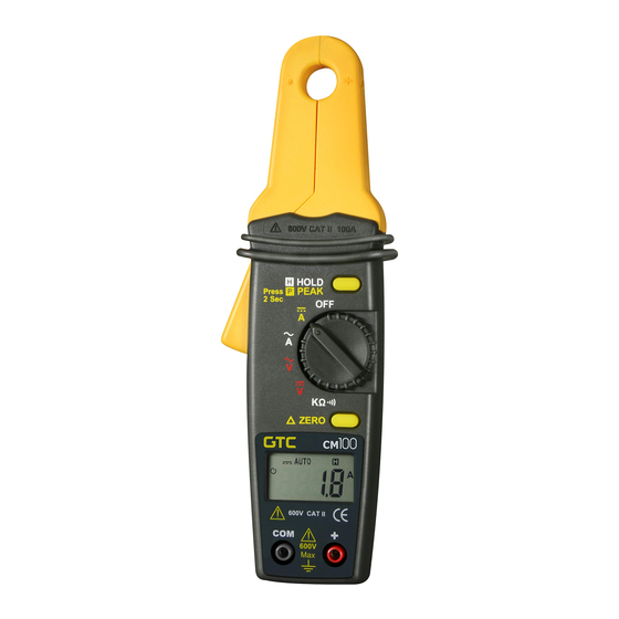
4.1 INSTRUMENT DESCRIPTION
1) Current sensing clamp
2) Safety protection ring
3) Clamp opening handle
4) LCD Display
5) COM input terminal
6) Positive input terminal
7) Zero button
8) Function selection knob
9) Peak/Data hold button
4.2 LCD Screen Description
Relative Indicator
AC/DC Indicator
Low Battery
Auto Power Off
4.3 Current Measurement
CAUTION: Remove all test leads connected to the
4.3.1 DC Current Measurement
Set the function selector knob to
the
will appear in the display. Open the clamp by pressing the clamp
opening handle, insert the cable or wire inside the current sensing clamp,
and then close the clamp and read from the LCD screen.
4.3.2 AC Current Measurement
Set the function selector knob to
clamp opening handle, insert the cable or wire inside the current sensing
clamp, and then close the clamp and read from the LCD screen.
150 Arms
150 Arms
660 Vrms
660 Vrms
660 Vrms
660 Vrms
CM
1
2
3
4
5
AUTO
P H
Digital Reading
instrument before proceeding with this test.
(DCA) and press the Zero button,
(ACA). Open the clamp by pressing the
i
i
600V CATII 100A
HOLD
H
PEAK
Press
P
2 Sec
OFF
A
A
V
V
ZERO
P H
A
600V CATII
300V CATIII
COM
600V
Incorrect
100
600V CATII
300V CATIII 600A
9
HOLD
H
PEAK
Press
P
2 Sec
OFF
A
8
A
V
V
7
ZERO
P H
A
600V CATII
300V CATIII
COM
6
600V
Peak Hold
Data Hold
Continuity
A
Ampere Indicator
V
Voltage Indicator
Ohm Indicator
i
i
600V CATII 100A
HOLD
H H
PEAK
Press
P
2 Sec
OFF
A
A
V
V
ZERO
P H
A
600V CATII
300V CATIII
COM
600V
Correct
Advertisement
Table of Contents

Subscribe to Our Youtube Channel
Related Manuals for GTC CM100


Summary of Contents for GTC CM100
-
Page 1: Instrument Description
1. SAFE TY RULES 4. OPERATION This meter is designed for indoor use at temperatures between 0°C to 40°C and • 4.1 INSTRUMENT DESCRIPTION altitudes up to 2,000m. • To ensure that the meter is used safely, follow all safety and operating instructions in 1) Current sensing clamp this operation manual. -
Page 2: Voltage Measurement
Proceed to connect the test leads #121 - 7350 72nd Street Tel.: (604) 952-6699 across the component or circuit under test. Read resistance in Ohms on Delta, BC V4G 1H9 Fax: (604) 952-6690 the LCD screen Canada www.gtc.ca © Copyright 2017 General Technologies...
Need help?
Do you have a question about the CM100 and is the answer not in the manual?
Questions and answers