Advertisement
Quick Links
Instructions
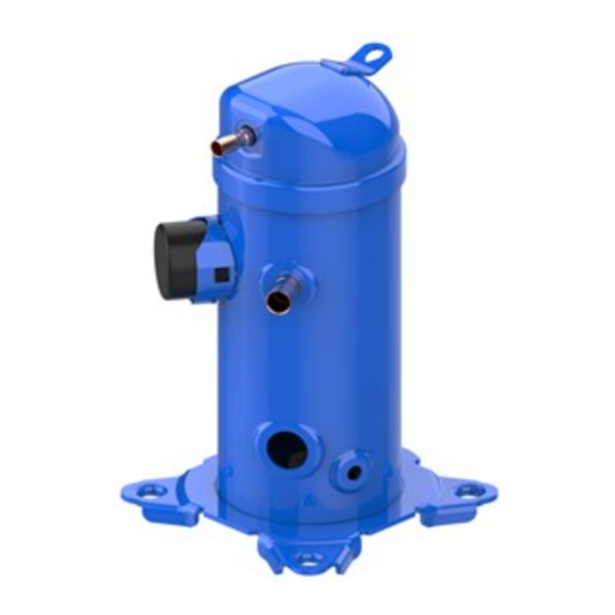
H series compressors
Operating limits
Hrm/HLm/HCm-HrP/HLP/HCP model variation T
(r22/407C)
70
65
60
55
SH 11K
50
45
40
35
30
25
20
-30
-25
-20
-15
-10
-5
0
Evaporating Temperature (°C)
HrH/HLH/HLJ/HCJ
model variation T (r410A)
70
65
HCJ120 & HCJ121
60
55
SH 5K
50
SH 11K
45
40
35
30
25
20
-30
-25
-20
-15
-10
-5
0
Evaporating Temperature (°C)
Hrm/HLm/HCm - HrH/HLH/HLJ/HCJ
model variation U (r22 / r410A)
70
65
60
55
50
SH 11K
45
40
35
30
25
20
-30
-25
-20
-15
-10
-5
0
Evaporating Temperature (°C)
HHP (r407C)
70
65
SH 5K
60
55
SH 10K
50
45
40
35
30
25
20
-30
-25
-20
-15
-10
-5
Evaporating Temperature (°C)
When HRM compressors are used with R417A, the
factory charged oil must be replaced by PVE oil 320HV
(120Z5034).
FRCC.PI.015.A4.02 - December 2014 - 8510274P01A
A
B
C
D
E
Electrical connections
Quick connect spade terminals
5
10
15
push
5
10
15
used for its designed purpose(s)
and within its scope of application
(refer to «operating limits»). Consult
Application guidelines and datasheet
available from cc.danfoss.com
5
10
15
The compressor is delivered under nitrogen gas pressure
(between 0.3 and 0.4 bar / 4 and 6 psi). Do not disassemble
bolts, plugs, fittings, etc... unless all pressure has been
relieved from the compressor.
1 – Introduction
These instructions pertain to the Danfoss scroll
compressors used for HVAC systems. They provide
necessary information regarding safety and proper
usage of this product.
0
5
10
15
2 – Handling and storage
• Handle the compressor with care. Use the dedicated
handles in the packaging. Use the compressor lifting
lug and use appropriate and safe lifting equipment.
Quick connect spade terminals
P terminal box type
P & T terminal box type
C
T₁
S
T₂
R
T₃
ring connect screw terminals
Ring connect screw terminals
C terminal box type
C & Q terminal box type
push
Installation and servicing of the compressor by qualified personnel only. Follow these
instructions and sound refrigeration engineering practice relating to installation,
commissioning, maintenance and service.
The compressor must only be
A: Model number
B: Technical number
C: Serial Number
F
D: Manufacturing year
G
E: Internal protection
H
F: Supply voltage range
I
G: Run capacitor
J
H: Locked rotor current
Maximum operating current
I:
Lubricant type and nominal charge
J:
Approved Refrigerant
Single phase
C
Line
C
Line
R
Brazed connection
Connec.
Models
size
HRM032-042
Suction
HRP034-042
3/4"
HRM/HRP045-047
Disch. 1/2"
HRH029-040
HRM/HRP048-060
HLM/HLP068-075
Suction
HRH041-056
7/8"
HLH061-068
Disch. 1/2"
HLJ061-068
Suction
push
HLM/HLP078-081
7/8"
Disch. 3/4"
HCM/HCP094-120
Suct. 1"1/8
HCJ090-121
Disch. 7/8"
Never operate
Under all circumstances, the
compressor without
EN378 (or other applicable local
terminal box cover in
safety regulation) requirements
place and secured.
must be fulfilled.
Wear protective goggles and
work gloves.
The compressor must be handled
with caution in the vertical
position (maximum offset from
the vertical : 15°).
• Store and transport the compressor in an upright
position.
• Store the compressor between -35°C and 70°C
(31°F and 158°F).
• Don't expose the compressor and the packaging
to rain or corrosive atmosphere.
3 – Safety measures before assembly
Never use the compressor in a flammable atmosphere.
• Mount the compressor on a horizontal flat surface
with less than 7° slope.
© Copyright Danfoss | Commercial Compressors | 2014.12
PSC wiring
Run
Capacitor
R
CSr wiring
5
Potential
Relay
2
1
Start
Run
Capacitor
Capacitor
Rotolock connection
Connec.
Models
size
-
-
HRH044-
056
Suct. 1"1/4
HLH061-
Disch. 1"
068
HLJ072-083
-
-
-
-
Advertisement

Related Manuals for Danfoss H Series


Summary of Contents for Danfoss H Series
- Page 1 Use the compressor lifting factory charged oil must be replaced by PVE oil 320HV with less than 7° slope. lug and use appropriate and safe lifting equipment. (120Z5034). FRCC.PI.015.A4.02 - December 2014 - 8510274P01A © Copyright Danfoss | Commercial Compressors | 2014.12...
- Page 2 Danfoss can accept no responsibility for possible errors in catalogues, brochures and other printed material. Danfoss reserves the right to alter its products without notice. This also applies to products already on order provided that such alterations can be made without subsequential changes being necessary in specifications already agreed.
- Page 3 Evaporating Temperature (°C) 切勿在易燃环境中使用压缩机。 • 处理压缩机时请小心。 请使用包装箱内的 当 HRM 压缩机与 R417A 一起使用时,必须将出 • 将压缩机安装在坡度小于 7° 的水平面 专用把手。 请使用压缩机的吊环,并采用 厂充注的油脂更换为 PVE 油 320HV (120Z5034) 上。 恰当且安全的起重设备。 。 FRCC.PI.015.A4.41 - December 2014 - 8510274P01A © Copyright Danfoss | Commercial Compressors | 2014.12...
- Page 4 冷剂,并尽可能远离压缩机。 必须在压缩 • 切勿让充注气瓶一直与回路连接。 机运行过程中执行该过程。 • 请勿对系统进行过量充注。 • 切勿将制冷剂排到大气中。 • 立刻安装场地之前,执行常规安装检查, 对于目录、手册及其他印刷材料中可能出现的错误,Danfoss 不承担任何责任。 Danfoss 保留修改产品的权利,怒不另行通知。 这也适用于已经订购的产品,前提是此类修改不会对已确定的 产品规格带来极大的改动。 本材料的所有商标是相应公司的财产。 Danfoss 和 Danfoss 徽标是 Danfoss A/S 的商标。 保留所有权利。 FRCC.PI.015.A4.41 - December 2014 - 8510274P01A © Copyright Danfoss | Commercial Compressors | 2014.12...