Table of Contents
Advertisement
Advertisement
Table of Contents

Related Manuals for Thermopatch HS-4-C


Summary of Contents for Thermopatch HS-4-C
- Page 1 Y600 Thermo-Seal-Jet HS-4-C V. 2.2 January 2021 ENG original version...
- Page 2 Congratulations and welcome to the ever growing number of Thermopatch users. You have acquired a machine which has been manufactured by Thermopatch with the greatest possible care. We are confident that you will be enjoying the use of this machine for a long time.
-
Page 3: Table Of Contents
1.2 Warranty 3. Assembly and installation 3.1 Installing the HS-4-C 3.2 Electrical Requirements 4. Operating manual 4.1 How to operate the HS-4-C 4.2 The HS-4-C display 4.3 Starting up 3.2 Functionality 5. Overview of safety measures and warnings 5.1 Safety 5.2 Warning symbols... -
Page 4: General Description
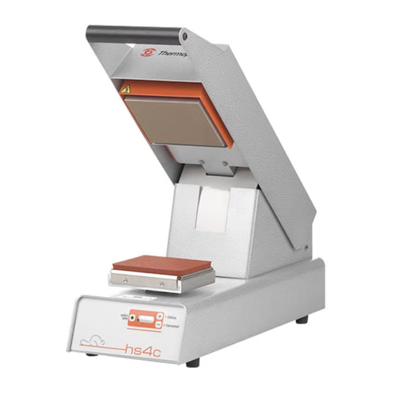
The manual HS-4-C desktop heat seal press is used for applying identification labels, emblems and transfers on textiles. The HS-4-C has a powerful heating element. The top plate heats up in seconds and is ready for use in no time from sleep mode. -
Page 5: Assembly And Installation
Take the machine out of the box and put it on a worktable near an earthed wall socket. Ensure that there is sufficient free space around the HS-4-C. Also ensure that there are no items near the HS-4-C, which are sensitive to heat radiation. -
Page 6: Operating Manual
4.2 The HS-4-C display 4.3 Starting up You can start operating the Thermoseal HS-4-C as soon as it is connected to the electricity mains. Switch on the HS-4-C by pressing the on/off (I-0) switch, which is placed on the back of the machine, to “on (I)”. Wait until the set temperature has been reached, which will take about one minute. - Page 7 Heater Element and no changes will be saved. Procedure to change desired Sealing Cycle Time: The SEALING CYCLE TIME of the HS-4-C heat seal machine has been set at the factory to 12 seconds. To change the SEALING CYCLE TIME, please follow the procedures below: 1.
- Page 8 Normally, higher pressures will produce more effective heat seals. However, the use of excess pressure may force adhesive through the fabric, with an undesired result. Difficuly in locking the Seal Arm Handle of the HS-4-C machine in a closed position is anindication of too much inter-platen pressure. To preventexcess pressure when sealing thick garments, screw the Lower Press Platen all the way down.
-
Page 9: Overview Of Safety Measures And Warnings
5. Overview of safety measures and warnings 5.1 Safety At normal usage no problems are to be expected. Regardless that, we state underneath a few pointers which will limit existing risks to a minimum. • Unplug the machine from the wall socket whenever you are maintaining or cleaning the machine. -
Page 10: Technical Specifications
6. Technical specifications 6.1 Specifications of the HS-4-C Power supply 230 Volt Power 600 Watt Operating temperature 204 ° C Temperature range 20 - 230 ° C Press time range 1 - 60 sec. Machine height, open 550 mm Machine height, closed... -
Page 11: Transport And Storage
7. Transport and storage 7.1 Transport When the machine needs to be moved, Thermopatch recommends to use the original packaging. 7.2 Storage When the machine needs to be stored, Thermopatch recommends to use the original packaging. The machine should preferably be stored on a pallet, off the floor, in dry conditions. -
Page 12: Technical Annexes
• Excess pressure. down. Handle does HS-4-C. • Motor is defective. not return at end of • See III. Operating the cycle (HS-4-C). • Linkage or gas spring is HS-4-C. binding or broken. • Replace • Springs are weak. •... -
Page 13: Replacement Parts
Error codes: • Error 1 = Temperature sensor short (0 Ohm) • Error 2 = Temperature sensor broken • Error 3 = Error in Eprom: the processor has no access to the memory for saving or reading of information. • Error 4 = Motor timed out, not in position or motor switch error:The correct position of the Cam Arm Motor cannot be detected. -
Page 14: Drawings And Parts (English Only)
9.3 Drawings and parts (English only) Please find addtional information on: www.thermopatch.com, equipment and parts. Power entry module ITEM # DESCRIPTION Part Number Electrical Chassis 46326 Power Entry Module Assembly (without fuses) 46453 Fuse Drawer P/O 46453 230 VAC 3.15 AMP Fuses... - Page 15 Controller board ITEM DESCRIPTION Part Number Electrical Chassis 46326 #4-40unc x ¼” Socket Hex Cap Screw 21063-02-C #4 Spring Lockwasher 21031-03-C Controller Board 46411...
- Page 16 Heater element ITEM # DESCRIPTION Part Number ¼ 20unc x 5/8” Socket Hex Cap 21063-05-K Screw M5 Hex Nut 21045-07-A M5 Spring Lockwasher 21046-06 Pivot Block 46378 Pivot Block Pin 46379 Heater Unit Assembly SPAHS40000 Teflon Cover 46375 Compression Spring 24075-36...
- Page 17 Platen assembly ITEM DESCRIPTION Part Number Platen Assembly 43941 Rotating Platen Base 43663...
- Page 18 Extension spring assembly ITEM DESCRIPTION Part Number Extension Spring 24080-35 Bumper 24091-44 Base Frame Assembly 47263...
- Page 19 Gas spring mounting ITEM # DESCRIPTION Part Number Top Cover Mounting Plate 46312 Gas Spring Bracket 46374 Gas Spring 24091-48 #10 Flat Washer 21023-01 #10 Spring Lockwasher 21012-07-C #10-32unc x 3/8” Socket Hex Cap Screw 21063-03-J Gas Spring Ball Joint 24901-77 5/16”...
- Page 20 Seal arm release mechanism ITEM DESCRIPTION Part Number #4-40unc Hex Nut 21051-03-A #4-40 Spring Lockwasher 21021-03-C CAM Release Arm Switch 20055-62 #8-32unc x 3/8” Hex Socket Cap Screw 21063-03-G #8 Spring Lockwasher 21021-06-C Cam Arm Switch Bracket 47187 #10-32unf x 3/16” Set Screw, Socket Hex Cup 21011-04-K Point Cam Release Lobe...
- Page 21 Press arm assembly ITEM DESCRIPTION Part Number #8-32unc x 3/8” Button Head Socket Screw 21029-48 #8 Spring Lockwasher 21021-06-C Close Out Cover 46363 E Style ½” Diameter Retaining Ring 21025-26 Thrust Washer OD= 1”, ID= 0.5” 21022-13 Link Arm Pivot Shaft 46328 Close Out Cover Bracket 46364...
- Page 22 Electric wiring schematic Chassis Gnd GRN/YEL Power Entry Module Fuses: [2] 3.15 Amp L1 BLK L2 WHT Controller Board Press Arm Jumper Wire Harness Wire Plug 6 YEL 5 YEL PT1600 Solid State High Limit Heater Unit Wire Harness Relay Thermostat Plug L1 WHT...
-
Page 23: Recycling
10. Recycling Choose to dispose of the machine responsibly when it has reached its end of life. Electrical machinery, accessories and packaging should be recycled as much as possible in an environmentally responsible manner. • Dismantle the machine groups: steel parts / pneumatic components / electrical components •... -
Page 24: Declaration Of Conformity
Thermopatch B.V. Draaibrugweg 14 1332 Almere Netherlands Declare under our own responsability that the heat sealing machine: Thermopatch HS-4-C which this declaration refers to, is in accordance with the conditions of the following Directive(s): 2014/30/EU (emc directive) 2014/35/EU (Low tension directive) -
Page 25: Disclaimer
Using sealing pads of any format other than the standard supplied with the machine may render the CE declaration invalid. Thermopatch accepts no responsibility for any damage or injury that may result from possible non-conformity. Choosing an alternative configuration other than the standard is at the customer’s own... - Page 26 Thermopatch Canada Inc Canada T +15 19 748 50 27 F +15 19 748 15 43 broussel@thermopatch.com Thermopatch UK United Kingdom T +44 15 397 22 122 F +44 15 397 21 000 team@thermopatch.uk V. 3.0 ENG Jan2014 V. 4.0 ENG Jan2015...
Need help?
Do you have a question about the HS-4-C and is the answer not in the manual?
Questions and answers