Advertisement
Quick Links
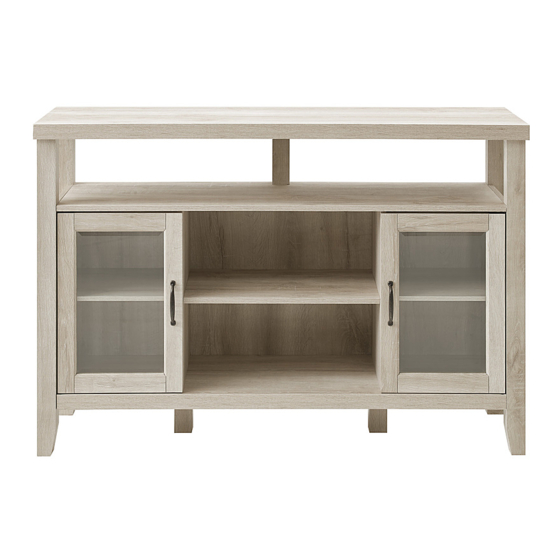
Item # : BU52JOR
Assembly Instructions
Please visit our website for the most current instructions, assembly tips, report damage,
or request parts. www.walkeredison.com
Revised 01/2018
Copyright © 2018, by Walker Edison Furniture Co., LLC. All rights reserved.
P.1
Advertisement

Related Manuals for Walker Edison BU52JOR


Summary of Contents for Walker Edison BU52JOR
- Page 1 Item # : BU52JOR Assembly Instructions Please visit our website for the most current instructions, assembly tips, report damage, or request parts. www.walkeredison.com Revised 01/2018 Copyright © 2018, by Walker Edison Furniture Co., LLC. All rights reserved.
- Page 5 Insert wooden dowel (A) to bottom panel (2) and part (19). Secure cam bolt (B) to top panel (1). Insert wooden dowel (A) to shelf (11,12), and side panel (9,10). Secure cam bolt (B) to shelf (11), and side panel (9,10).
- Page 6 Insert wooden dowel (A) to part (3,4,5,6), and side panel (7,8). Secure cam bolt (B) to part (3,4,5,6). Insert side panel (7,8) into part (3,4,5,6), then insert and secure cam lock (C) to side panel (7,8) to lock it.
- Page 7 Use wrench (E) to secure leg (18) to bottom panel (2) with bolt (D), and secure part (19) to shelf (11). Insert shelf (12) into side panel (9,10), then insert and secure cam lock (C) to shelf (12) to lock it.
- Page 8 Slide back panel (13) into grooves as per diagram. Use wrench (E) to secure bottom panel (2) to side panel (9,10) with bolt (D).
- Page 9 Slide back panel (13) into grooves as per diagram. Insert side panel (9,10) into shelf (11), then insert and secure cam lock (C) to side panel (9,10) to lock it.
- Page 10 Slide back panel (14) into grooves as per diagram. Insert bottom panel (2) and shelf (11) into side panel (7) and part (3,5), then insert and secure cam lock (C) to bottom panel (2) and shelf (11) to lock it.
- Page 11 Insert bottom panel (2) and shelf (11) into side panel (8) and part (4,6), then insert and secure cam lock (C) to bottom panel (2) and shelf (11) to lock it. Insert top panel (1) into part (3,4,5,6,19), then insert and secure cam lock (C) to part (3,4,5,6,19) to lock it.
- Page 12 Place sticker (L) over holes as per diagram. Secure plastic wedge (N) to back panel (13,14) with screw (O).
- Page 13 Insert shelf support pin (F) into side panel (7,8,9,10), then place shelf (17) on top of support pin (F). Secure bolt (U) to door (15,16), door hinge (J) to door (16) and door hinge (K) to door (15) with screw (G).
- Page 14 Secure handle (H) to door (15,16) with bolt (I). Place plastic pivot (M) over holes as per diagram.
- Page 15 Insert door hinge (J,K) into panel hole as per diagram. Slide door (15,16) onto door hinge (J,K) as shown in diagram and secure it with screw (G). Place unit in desired location and mark the wall for anchor location. Insert plug (S) into wall as per diagram.
- Page 16 Secure flat plate (Q) to as shown in diagram with screw (R). Secure product to wall with screw (T).
Need help?
Do you have a question about the BU52JOR and is the answer not in the manual?
Questions and answers