Table of Contents
Advertisement
Advertisement
Table of Contents

Summary of Contents for Weber DVH 600
- Page 1 Operating and Maintenance Manual DVH 600 0140202...
-
Page 3: Table Of Contents
Table of contents Introduction Safety guidelines Graphic presentation Device description Technical data Activities prior to starting work Starting Driving and compacting Shutting down Maintenance overview Maintenance work Operating fluids and fill levels Troubleshooting Storage Hydraulic circuit diagram... -
Page 4: Introduction
This operating and maintenance manual must always be available at the implementation site of the roller. If necessary you can obtain additional information from your authorized WEBER dealer, or you can obtain information from one of the contact addresses on the last page. -
Page 5: Safety Guidelines
Malfunctions that impair safety must be eliminated without delay. The DVH 600 roller is designed exclusively for compacting – bituminous material (road surfaces); and – light compaction tasks for earth works. - Page 6 (tunnels, caves, etc.). Exercise particular caution when operating the engine in the vicinity of people and livestock. Maintenance and repair work Only use original Weber spare parts to ensure reliable and safe operation for maintenance or repair work. Hydraulic hose lines must be checked at regular intervals in accordance with standard engineering practice, or they must be replaced at appropriate intervals, even if no signs of safety-relevant defects are present.
- Page 7 Inspection Rollers must be inspected in accordance with the corresponding implementation conditions and operating conditions, as needed; however an inspection to ensure operationally safe status must be performed by an expert at least once a year. The results of the inspection must be recorded in writing and must be stored at least until the next inspection.
-
Page 8: Graphic Presentation
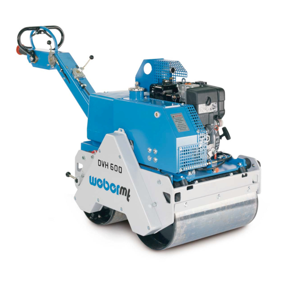
Graphic presentation Overall view DVH 600 1 Manual guidance rod 9 Scraper 2 Hydraulic tank 10 Drums 3 Lifting ring 11 Chain guard 4 Water tank 12 Parking brake 5 Fuel tank 13 Gas lever 6 Engine 14 Vibration lever... -
Page 9: Device Description
Device description The DVH 600 roller is used for compaction work in road building applications. Drive The compactor is powered by an air-cooled Kohler diesel engine. Function Start the Kohler diesel engine with the attached reversing starter. The two drums are hydrostatically powered via chains. The chain drive is executed individually on each bandage. -
Page 10: Technical Data
Technical data DVH 600 Weight Dead weight (in kg) Operating weight CECE in kg Average stat. line load (in N/cm) 31.7 Dimensions Overall length (in mm) 1885 Overall width (in mm) Height (in mm) 1046 Drum width (in mm) Drum diameter (in mm) - Page 11 DVH 600 Noise emissions in accordance with 2000/14/EC Sound pressure level L ascertained in accordance with EN 500, in dB (A) Sound power level L ascertained in accordance with EN ISO 3744 and EN 500, in dB (A) Vibration values...
-
Page 12: Activities Prior To Starting Work
Activities prior to starting work Transport When transporting the soil compactor on a vehicle, secure it with suitable restraints. Arrest the manual guidance rod (1) with the spring bolt (2). Fit the crane hook into the lifting ring (1) and lift the machine onto the desired means of transport. -
Page 13: Starting
Check the hydraulic oil level Check the hydraulic oil level when the machine is at operating temperature. The correct oil level is reached when the oil is in the middle of the view glass. No hydraulic oil is consumed during operation. If the oil level drops, you must check the hydraulic system for leaks Starting To start, push the vibration lever (1) to the left into the off... -
Page 14: Driving And Compacting
Driving and compacting Bring the gas lever (1) into full-throttle position. Push the parking brake lever (1) into vertical position (disengage). Open the water shut-off valve (1). Push the drive bar (1) into the desired direction of travel. Move the vibration adjustment lever (2) as far as it will go to position ( Forward = Press the drive bar forward... -
Page 15: Shutting Down
The roller will come to an immediate stop as soon as the drive lever (1) is released. If the operator bumps against the crush guard (3) when moving in reverse, the machine comes to a stop. Through swinging out the drive lever (1) forward in the direction of travel, the crush guard is again lifted up. - Page 16 Move stop lever (1) to the left until the engine comes to a standstill. During breaks – even if they are short – the machine must be shut down. Parked devices that represent an obstacle must be safeguarded against through conspicuous measures.
-
Page 17: Maintenance Overview
Maintenance overview Maintenance interval Maintenance point Maintenance activity After the first Hydraulic system – Change hydraulic oil filter 50 operating hours Engine – Change the engine oil Every 8 operating hours / Air filter – Clean air filter insert, check for daily damage, replace if necessary Hydraulic system... - Page 18 The regulations of the engine manufacturer must be complied with in addition to the above main- tenance overview! Work must be carried out using regulation tools, and the operating and maintenance manual must be complied with for all work. Repairs exceeding the scope of regular maintenance may only be performed by trained personnel acting in accordance with our repair manual.
-
Page 19: Maintenance Work
Maintenance work Change the engine oil Open the screw cap (1) of the oil filler neck. Screw the oil drain pipe onto the engine drain valve (1) and drain off the oil. Only drain engine oil when at operating temperature. After emptying completely, unscrew the oil drain pipe from the drain valve and fill with oil in accordance with the specification. - Page 20 Change the fuel filter Pull the fuel line (2) off the fuel filter (1) on both sides. Replace the filter with a new filter element. If lubricating oils and fuel come into contact with skin, they can cause skin cancer. Upon contact with the skin, clean affected skin with suitable cleaning agent without delay.
- Page 21 Check V-belt Move vibration adjustment lever (1) to position ( Remove the water tank (1). Check the V-belt (1) for cracks, damaged flanks, and wear. If there is excessive wear – replace the V-belt as specified in the repair manual. After inspecting the V-belt –...
- Page 22 Lubricate the drive chain Remove the chain guard (1). Lubricate the chains (1) as needed and in accordance with the specification. Refit the chain guard when finished lubricating the chains. Check / tighten drive chains Remove the chain guard (1). Check the tension of the chains (1).
- Page 23 Lift hydraulic motor through the opening (1) until the chains (2) have reached the desired tension. Securely tighten the screws (1). Fasten the chain guard (1). Work must be carried out using regulation tools, and the operating and maintenance manual must be com- plied with for all work.
- Page 24 Change hydraulic oil Always drain the hydraulic oil when the roller is at a standstill. Open the tank cap (1). Remove the protective cap (1). Screw the drain hose onto the drain connection (2). As soon as the drain hose is screwed on, the drain valve will open.
- Page 25 Change hydraulic oil filter Remove the protective grating (1). Drain hydraulic oil. Unscrew the hydraulic oil filter (2). Danger of scalding due to hot hydraulic oil. Lightly oil the rubber seal of the hydraulic oil filter. Screw on new hydraulic oil filter. Only hand tighten the hydraulic oil filter.
- Page 26 Lubricate the vibration shaft Clean the lubricating nipple (1) on both sides of the vibration shaft. Place the grease gun on the lubricating nipple of the vibration shaft. Press grease that complies with the specification into the bearing housing. Adjust, clean the scraper Loosen the screws (1) at the front / rear of the roller.
-
Page 27: Operating Fluids And Fill Levels
Operating fluids and fill levels Assembly Operating material Summer Winter Quality Engine SAE 10 W 40 1.0 l (– 10 ~ + 50 °C) Engine oil API – CD CE or SHPD or CCMC – D2 – D3 – PD1 Fuel tank Diesel Winter diesel fuel... -
Page 28: Storage
All bare parts / accelerator / accelerator – Oil / grease control cable / fastening bolts If the machine is to be stored for longer than six months, then contact the Weber service organization to discuss additional measures. -
Page 29: Hydraulic Circuit Diagram
Hydraulic circuit diagram 5 Oil tank 4 Hydraulic motor 3 Filter change cartridge 2 Axial piston adjustment pump 1 Diesel / gasoline engine DVH 600-2 Ident no.: 085000015... - Page 32 Weber Maschinentechnik GmbH Im Boden 5-8, 10 · 57334 Bad Laasphe · Germany Phone +49 2754 398 0 · Fax +49 2754 398 101 info@webermt.de · www.webermt.de 085103011-104 / DVH 600_2020-05 Original instructions...
Need help?
Do you have a question about the DVH 600 and is the answer not in the manual?
Questions and answers