Table of Contents
Advertisement
Available languages
Available languages
Quick Links
Advertisement
Table of Contents

Related Manuals for Brunton ECLIPSE 8099


Summary of Contents for Brunton ECLIPSE 8099
- Page 1 ECLIPSE BRUNTON INSTRUCTION MANUAL MANUEL D'INSTRUCTIONS...
- Page 2 Copyright 1998, The Brunton Company A subsidiary of Silva Production, AB Printed in U.S.A. form 62-8099 rev 9951...
-
Page 3: Table Of Contents
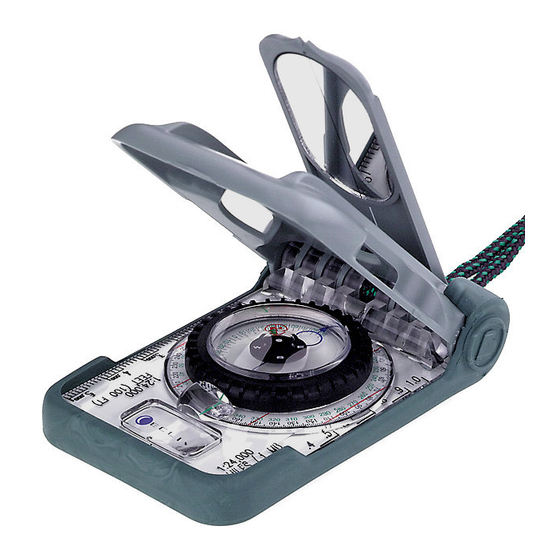
Section 1 – ORIENTATION (Brunton Eclipse 8099) Section 2 – MAGNETIC DECLINATION Section 3 – 1° GRADUATED DIAL Section 4 – FIELD BEARING (Forward & Reverse Sighting) Section 5 – DIRECTION OF TRAVEL Section 6 – TOPOGRAPHIC MAP Section 7 – MAP BEARING (Map & Compass Alignment) Section 8 –... - Page 4 1 – Orientation: Brunton Eclipse 8099 The Eclipse 8099 compass is a sighting instrument which uses the Earth’s magnetic field to display a bearing (direction) in degrees. The Eclipse 8099 also contains three clinometer scales to meas- ure angles from horizontal (0°).
-
Page 5: Section 3 – 1° Graduated Dial
Read bearing and inclination at this line. 1.6 Rubber Shoe (Fig 1) The removable rubber shoe encloses and protects the Eclipse 8099 and a set of quick refer- ence cards (described in 1.11). Also, the rubber shoe can be used as a pencil eraser for maps. - Page 6 Eclipse 8099 for magnetic declination. 1.13 Clinometer Index Mark (Fig 3) Use the clinometer index mark in combination with the...
-
Page 7: Magnetic Declination
It is important to note magnetic declination at your position, because magnetic declination varies and fluctuate slowly at different rates, around the world. (Fig 4) Contact Brunton for current information at (307) 856-6559, or e-mail us at support@brunton.com. Figure 4... - Page 8 1. Find the magnetic declination at your current position, from a map or chart. 2. Remove rubber shoe, and open both covers. 3. Position the Eclipse 8099 with bottom of clear base facing you. (Fig 6) True North Magnetic North...
-
Page 9: Field Bearing
4. Locate declination scale. 5. Grasp azimuth ring in one hand, and the vial in the other. (Fig 6) 6. Hold azimuth ring stationary, and rotate vial until the arrow on the to the value of magnetic declination at your current position. ·... -
Page 10: Section 5 – Direction Of Travel
"N". · Make sure base is level and sighting lines and peep sight are aligned. 5. Position Eclipse 8099 close enough to read field bearing in magnified index lens. · Read bearing from green scale at the green line –... -
Page 11: Section 6 – Topographic Map
7 – Map Bearing Whether in the field or at home, it is possible to determine a bearing from one position to another directly from a map. The Eclipse 8099 provides two methods of finding map bearings – map alignment and compass alignment. - Page 12 This is a popular method because it is possible to compare the map to the actual terrain. The following examples use a USGS topographic map. 1. Remove rubber shoe. 2. Adjust for magnetic declination. 3. Rotate azimuth ring until compass bearing reads 0° -- green scale, figure 15.
- Page 13 The topo-map is now aligned with true north. In the field, it is possible to compare the map to the actual terrain. Now, find the map bearing from one position to another. 6. Place a "point" at a starting position and an "X" at a destination. 7.
- Page 14 Figure 19 · Fill map with additional true north-south lines, spaced approximately 1 inch apart, parallel to map’s margin. (Fig 5. On the map, mark a start position with a "point" and a destination with an "X". 6. Draw a line connecting both marks.
-
Page 15: Section 8 – Triangulation
9. Keeping clear base stationary on the map, rotate azimuth ring until blue orienting circle points in a northerly direction, and the on graduated circle are aligned with the drawn true north-south lines. (Fig 21) 10. Read bearing from the green scale in magnified index lens. - Page 16 · See Section 4.1, Forward Mirror Sighting, for help. 6. With both covers open to 180°, place clear base of 8099 next to landmark ‘1’, on the map. 7. With green scale set to 320°, pivot compass around landmark ‘1’...
-
Page 17: Section 9 – Back Bearing
This section explains positioning on a 7.5 minute topographic map using Universal Transverse Mercator (UTM) grid (grid coordinate system) and latitude and longitude (spherical coordinate system). The Eclipse 8099 provides Universal Transverse Mercator (UTM) gird scales on the clear base and reference card 6. - Page 18 Mapped, edited, and published by the Geological Survey Control by USGS and USC&GS Topography by photogrammeteric methods from aerial photographs taken 1966. Field checked 1968 Polyconic projection. 1927 North American datum 10,000-foot grid based on Wyoming coordinate system, west zone 1000-meter Universal Transverse Mercator grid ticks, zone 12.
- Page 19 ‘X’. Remember, eastings always increase to the right, and northings always increase up. 10.2 Latitude And Longitude Coordinate System Latitude and longitude scales are not provided with the Eclipse 8099, but determining a position using a latitude and longitude scale, or a ruler is an essential navigation skill.
- Page 20 2. Identify and mark a position on the map with an ‘X’. 3. Use a 1:24,000 latitude-longitude scale to determine the coordinate position of the ‘X’ (not available with the Eclipse 8099). 00' 00" N. Latitude 00' 00" W. Longitude Latitude Increase Longitude Increase Figure 30 10.2.a -- Latitude And Longitude...
- Page 21 10.2.c -- Latitude Determination 1. Use the small rectangle that completely surrounds the ‘X’. 2. Place scale vertically, until bound by both horizontal latitude lines, and touches the ‘X’. (Fig 33) 3. At the ‘X’, add the value indicated by the scale (00’...
- Page 22 1. Remove rubber shoe to reveal the 5° clinometer scale, located on the end of the hinge. 2. Open the sight cover to at least 120°. 3. Hold the Eclipse 8099 at eye level with 5° scale facing you, and extend to arms length. 4. Sight object behind the Eclipse 8099. (Fig 35) 5.
- Page 23 3. At eye-level and arms length, position Eclipse 8099 on its side with the clinometer facing you and down. 4. Sight object behind the compass. (Fig 36) · Align either side of the clear base with object. 5. On the clinometer card, read...
- Page 24 3. Holding azimuth ring stationary, rotate vial until the arrow on the points to the clinometer index mark. 4. Place rubber shoe back on the base. Figure 41 9. Position the Eclipse 8099 close enough to read inclination in index lens. · Read 20° from the Figure 42...
-
Page 25: Height Measurement
We can now apply clinometer measurement to height measurement and percent grade. In order to calculate height of an object you must know distance to the object, and measure the angle of incli- nation with the Eclipse 8099. The following example uses the 1° graduated dial clinometer. 12.1 Level Ground Height Measurement 1. -
Page 26: Section 14 – Eclipse 8099 Specifications
Remember to readjust for magnetic declination before sighting a bearing. 13 – Additional Information Before heading into the field, practice using the Eclipse 8099 and a map in a familiar area. Also, carefully re-read the instruction manual to gain a full understanding of Eclipse 8099 applications. - Page 28 Section 11 – INCLINAISON (charnière, carte et limbe) Section 12 – CALCUL DE LA HAUTEUR (terrain plat et incliné) Section 13 – RENSEIGNEMENTS COMPLÉMENTAIRES Section 14 – SPÉCIFICATIONS TECHNIQUES DU MODÈLE ECLIPSE 8099 ECLIPSE 8099 MANUEL D’INSTRUCTIONS Page(s) : 27 - 28...
- Page 29 1 – ORIENTATION : Brunton Eclipse 8099 La boussole Eclipse 8099 est un instrument de visée qui permet de calculer un relèvement (direc- tion) en degrés par le biais des champs magnétiques de la Terre. Le modèle Eclipse 8099 renferme également trois échelles clinométriques afin de mesurer les angles à partir de l’horizontale (0...
- Page 30 (Figure 2) [1.10 - Clinometer Arrow] Située à l’intérieur de la fiole, la flèche pondérée verte boussole Eclipse 8099 est positionnée sur le flanc. Combinez l’utilisation de la flèche clinomètre et pointeur en forme de cercle bleu pour mesurer l’angle d’inclinaison.
-
Page 31: Déclinaison Magnétique
à un taux variable autour de la planète. (Figure 4) Appelez Brunton pour obtenir des variations de déclinaison exactes au 1-307-856-6559 ou communiquez avec nous par courrier électronique à HYPERLINK mailto: support@brunton.com... - Page 32 5. Tenez le cadran azimutal d’une main et la fiole de l’autre (Figure 6). 6. Tout en maintenant le cadran azimutal en place, faites pivoter la fiole jusqu’à ce que le pointeur en forme de cercle bleu soit orienté vers la donnée de déclinaison magnétique de votre position actuelle.
-
Page 33: Ligne De Marche
3. Placez la boussole à hauteur de la taille et le couvercle de visée pointé vers vous (Figure10). Figure 10 - p. 7 4. Visez l’objet dans le miroir et alignez la ligne de miroir avec celle réfléchie dans le couvercle. 5. -
Page 34: Relèvement Sur Carte
Que vous soyez à la maison ou sur le terrain, il possible de calculer le relèvement d’une position à une autre directement sur la carte. La boussole Eclipse 8099 offre deux méthodes pour déterminer les relèvements sur carte : alignement sur carte et alignement de la boussole. - Page 35 5. Faites pivoter la carte jusqu’à ce que le pointeur N encerclé rouge. - La base de la boussole doit demeurer le long de la marge de la carte. La carte topographique est maintenant alignée sur le nord géographique. Sur le terrain, il est possible de comparer la carte au terrain observé.
- Page 36 - Remplissez la carte de lignes additionnelles nord-sud en les espaçant d’environ 2,5 cm et les disposant de manière parallèle à la marge de la carte (Figure 19). Figure 19 - p. 11 Nord-sud lignes [North-South Lines] Long board [Straight Edge] 5.
-
Page 37: Relèvement Inverse
- 180 = 195 Grâce à la boussole Eclipse 8099, vous n’avez plus besoin de soustraire ou d’ajouter une valeur car elle contient deux échelles distinctes (Figure 25). Si vous visez un relèvement à l’aide de l’échelle verte, vous n’avez qu’à consulter l’échelle noire pouvez déterminer le relèvement inverse. - Page 38 7,5 minutes à l’aide d’un quadrillage UTM (système de coordonnées de quadrillage), de longitudes et de latitudes (système de coordonnées sphériques) La boussole Eclipse 8099 renferme les échelles de quadrillage UTM (Mercator Transverse Universel) sur la base transparente et la fiche de référence 6.
- Page 39 Figure 28 - p. 15 Échelle 1 : 24 000 [Scale: 1:24,000] Fuseau 11 [zone 11] Augmentation de l’abscisse [Easting Increases] Augmentation de l’ordonnée [Northing Increases] 3. Identifiez les amorces de quadrillage UTM et les étiquettes concernant l’origine de la carte.
- Page 40 Grâce aux quadrillages UTM, vous pouvez déterminer votre position avec exactitude à moins de 100 mètres sans utiliser un rapporteur. Une fois les amorces de quadrillage identifiées et les lignes de quadrillage tracées, vous n’avez qu’à estimer la distance au coin inférieur gauche du quadrillage qui entoure la marque X.
- Page 41 2. Identifiez et marquez une position sur la carte par un 3. Utilisez une échelle de longitude/latitude 1:24 000 afin de déterminer la position en coordonnées du (non disponible sur le modèle Eclipse 8099). 10.2c Détermination de la latitude 1. Utilisez le petit rectangle qui entoure complètement le X.
- Page 42 11 - Inclinaison L’inclinaison, parfois appelée pente, correspond à la différence angulaire par rapport à l’horizontale ). Le modèle Eclipse 8099 utilise trois échelles clinométriques et chacune est graduée en degrés. Les trois inclinomètres sont à charnière 5 11.1 Clinomètre à charnière 5 degrés Il s’agit de la méthode la plus rapide pour mesure l’inclinaison.
- Page 43 3. Positionnez la boussole à hauteur d’oeil et le miroir déplié vers l’extérieur et la gauche. 4. Au-dessus ou sous l’horizon, visez un objet à travers la mire (Figure 37). - Alignez la ligne du couvercle à la ligne du couvercle de visée. 5.
- Page 44 3. Tout en gardant le cadran azimutal immobile, faites pivoter la fiole jusqu’à ce que le pointeur bleu en forme de cercle soit orienté sur le repère du clinomètre. 4. Replacez le patin de caoutchouc sur la base. 5. Fermez le couvercle et ouvrez le couvercle de visée à 45 6.
- Page 45 5. Lisez le relèvement en référence de l’échelle noire 6. Positionnez la boussole à hauteur d’oeil et le miroir déplié vers l’extérieur et la droite. Reportez-vous à la section Angle descendant (11.3b) 7. Au-dessous l’horizon (à niveau, 0 ), visez la base de l’objet à travers la mire (Figure 43). 8.
- Page 46 Avant d’afronter les grands espaces, il est recommandé de pratiquer les lectures et les calculs dans un endroit familier en vpous servant de la boussole Eclipse 8099 et d’une carte. De plus, relisez attentivement votre manuel d’instructions afin de comprendre à fond les différentes apllica- tions de la boussole.
-
Page 47: Optional Information
TYPE OF STORE PURCHASED FROM: A. CATALOG B. ARCHERY D. SPORTING GOODS E. GIFT OTHER____________________________________________________ DO YOU OWN OTHER BRUNTON PRODUCTS? I DECIDED TO BUY THIS COMPASS BECAUSE OF... A. RECOMMENDATION D. SALESPERSON OTHER____________________________________________________ THIS COMPASS WILL BE USED PRIMARILY FOR... - Page 49 GET OUT THERE...
Need help?
Do you have a question about the ECLIPSE 8099 and is the answer not in the manual?
Questions and answers