Advertisement
Available languages
Available languages
Quick Links
BRUNTONCOMPASSGUIDE
Congratulations on purchasing a Brunton map compass, an easy to use,
A Practical
reliable navigation tool. Brunton recommends you read and understand the
basic navigational skills outlined in this instruction pamphlet before going afield.
Remember, prepare before you go. Tell others where you are going. Carry a
Field Guide
map and compass, a complete survival kit and know how to use them.
CAUTION: Your compass will only locate Magnetic North and bearings
for Map &
(directions) from your present location. You have to remember the direction
you have been traveling, the direction back to your starting point and keep
Compass
track of your present position on the map. IF YOU BECOME LOST, Admit it,
and try to remember where the map and the terrain matched. Backtrack
to that position with your compass. IF YOU STILL ARE LOST, Stay Put
and do not wander or panic. Shelter yourself from the elements. Wait for help
and be prepared to signal your position to rescuers.
1. How A Compass Works
Your compass is a navigational instrument that provides directions or bearings, using the Magnetic North Pole
as a reference. Following your BEARING and measuring the distance traveled (counting stride, time or plotting
locations on a map) is all that is required for successful navigation.
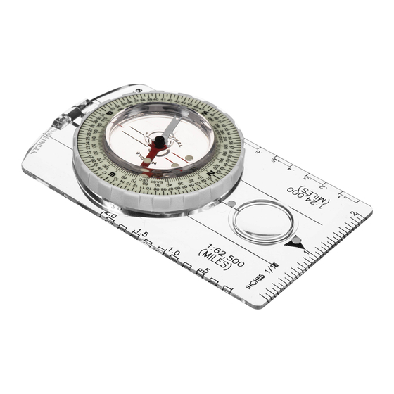
2. Getting to know your Compass (Figure 1)
Orienting Arrow
Declination Scale
Pointeur
Échelle de déclinaison
Travel Arrow
Flèche directionnelle
Vial
Fiole
Azimuth Ring
Cadran Azimutal
Map Scales
Échelles de la carte
Magnetized Needle
Aiguille aimantée
Figure 1
Magnetized Needle: Red/White painted cobalt steel needle. Permanently magnetized and suspended on a
bearing mount.
Azimuth Ring: White Rotating dial marked ( 2 degree increments) from 0-360° degrees. North "N" = 0°, South
"S" = 180°, East "E" = 90° and West "W" = 270° clearly indicated.
Orienting Arrow: Red/Black outlined arrow imprinted on clear vial bottom. Outlined orienting arrow is
adjustable eastward or westward for declination correction by rotating the clear vial independently from the white
azimuth ring.
Declination scale: Printed inside azimuth ring, 0-60 degrees marked every two degrees, East and West
declination.
Vial: Clear liquid filled plastic vial that surrounds magnetized needle. The liquid inside is used to slow and
stabilize the movement of the magnetized needle.
Map Scales: Black imprinted scales on base plate used to determine distance on maps. Refer to maps margins
for scale information. (i.e. USGS 7.5 min., 1:24,000 scale)
Travel Arrow: Black arrow on base plate used to point or sight the compass towards your destination or
direction.
Sighting Systems: Directional, and Mirrored.
Travel Arrow
Flèche directionnelle
Directional Sighting: Object or direction is
sighted using the "Travel Arrow."
Visée directionnelle : L'objet ou la direction est
relevé à l'aide du pointeur.
Models 9020, 8010 & 8020 (Figure 2A)
Mirrored Sighting: Object or direction is sighted
through "gun" sights while needle alignment and
azimuth ring are read in reflection of mirror.
Read Bearing Here
Visée à miroir : L'objet ou la direction est relevé au-dessus
du miroir par le biais de la mire (rainure en "V") au moment
Lisez le relèvement à
ce moment
où l'alignement de l'aiguille et du cadran azimutal est
prélevés en réflexion du miroir.
Figure 2B
Model 8040. (Figure 2B)
3. Sighting & Following a Compass Bearing
Hold your compass level in front of you, with the Base
Plate Travel Arrow pointing towards the direction you
wish to go. Do not point the compass with your hand.
Pocket
Turn your whole body. When your compass is held flat,
the Magnetized Needle will rotate freely and its RED
end will point towards Magnetic North. (Figure 3A)
Holding the compass level, rotate the
Graduated Dial until the Orienting Arrow and
Red "N" are aligned with the RED end of the
Use
Magnetic Needle. (Figure 3B)
Your Bearing or Direction of Travel can now
be read in Degrees at the Index Line on the dial at the base of the Travel
Arrow, which now points precisely to your destination. (Figure 3C)
Look up, sight a landmark (rock, tree, etc.) along the bearing path, using
the Travel Arrow as a guide. Take care not to mis-align the Magnetic
Needle. Keep it centered inside the Orienting Arrow. Now walk towards
the landmark. Repeat this procedure until you reach your destination.
(Figure 3D)
When you repeat this process, identify landmarks along your bearing path
(the further away the better) and walk to them. You can navigate around
difficult terrain such as streams and cliffs, while still maintaining your
original bearing.
If you are using a Brunton compass that has a Sighting Mirror, adjust the
mirror so that it reflects the entire compass dial as you look across the
Base Plate. Object or direction is sighted through "gun" sights while
needle alignment and azimuth ring are read in reflection of mirror. Turn the
Graduated Dial until the Orienting Arrow is aligned with the Magnetic
Needle. Your Bearing will be read at the Index line ("gun" sight) next to the
mirror hinge. Follow your Bearing as indicated above.
4. Using a Topographical Map
Topographical maps present a 3 dimensional picture of the land viewed
from above. Features are designated by color and symbol: Cultural
features or man-made (Black), water (Blue), vegetation (Green), and
elevation (Brown). Elevation is indicated by contour lines, on which every
point along the ground is at the same height above sea level. The closer
the contour lines, the steeper the slope. Every fifth line is darker and has a
number representing the height above sea level. Contour lines also show
the shape and form of the land. Maps are made to a scale, which
represents a proportion to the distance between points on the map and the
actual distance between the same points on
the ground. Large scale maps, such as a
1:24,000 U.S.G.S., on which features appear
big, show the most information for hiking and
camping. The legend at the base of the map
indicates the scale, contour interval and
special symbols shown. (Figure 4)
5. Understanding Declination
Declination (or variation) is the difference
between True North (to which maps are drawn) and
Magnetic North (as indicated by a compass). You
Must adjust for declination, East or West, when using
a compass with a map. Declination varies throughout
the world and is shown on topographical maps with a
diagram, identifying Magnetic North (MN) and the
degree variance from True North (TN). Magnetic fields
fluctuate slowly at varying rates around the world. It is best to use an up to
date map for current declination. Visit our web sight or call Brunton for an
accurate declination variance in a specific location. (Figure 5)
Figure 2A
6. Adjusting Compass for Declination
Identify the declination variance from your map. Grasp inside vial (orienting arrow) separately from white
azimuth ring. Rotate vial until the orienting arrow is pointing to the desired degree of declination on the
declination scale, East or West. (Figure 6) After you have adjusted your compass for declination, the
magnetized needle still points towards magnetic north. The white azimuth ring and bearings sighted with the
Figure 3A
compass now represent True North bearings.
Read Bearing Here
Lisez le relèvement à
ce moment
Figure 3B
Figure 3C
Figure 6
7. Quick Map Bearing: Brunton "ABC" System
A - Align Compass. Set declination and line up edge of compass connecting
present location with destination. Make sure Travel Arrow is pointing towards
destination. (Figure 7A)
B - Bearing is found by rotating the white azimuth ring until
North "N" and "red" grid lines on top of the azimuth ring
align with North and red grid lines on map. Bearing is
read where Travel Arrow intersects azimuth ring.
(Figure 7B)
C - Course is determined by rotating body (not
Figure 7C
compass) centering magnetized needle to
outlined orienting arrow and sighting a land
mark. (Figure 7C)
8. Map Bearings with "North" oriented map.
- Orienting Map to North
a.) Adjust compass for declination.
b.) Rotate Azimuth Ring so that North (0°) degrees intersects
with Travel Arrow.
c.) Place edge of compass on maps margin with Travel Arrow
pointing towards North end of the map. (Figure 8A)
d.) Without moving compass, rotate map until Magnetic Needle
is centered within outlined Orienting Arrow. (Figure 8B)
Figure 3D
Figure 8C
Figure 4
9. Establish a Map Bearing with "North" oriented map.
a.) Orient map to North.
Topographical Map Manufacturer
b.) Line up edge of compass connecting present location with
destination. Make sure Travel Arrow is pointing towards destination.
U.S.G.S. Maps: (800) 872-6277
(Figure 9A)
Trails Illustrated: (800) 962-1643
c.) Hold compass base and rotate Azimuth Ring until magnetized
DeLorme Mapping (207) 865 4171
needle is centered within outlined orienting arrow. (Figure 9B)
d.) Read bearing where Travel Arrow and Azimuth Ring intersect.
10. Field Bearing to Map with "North" oriented map.
a.) Orient map to North.
b.) Identify a landmark on map which can be sighted from
True North
your position.
Nord géographique
c.) Establish field bearing by sighting compass to
Magnetic North
landmark identified from map. (Figure 10A)
Nord magnétique
d.) Place edge of compass on maps' landmark. The
Travel Arrow should point towards landmark on map.
13 °
(Figure 10B)
While keeping compass edge on landmark, pivot compass until
230 mils
magnetized needle is centered within orienting arrow. Plot bearing on
map by drawing line from landmark using the edge of the compass.
(Figure 10C)
Figure 5
11. Triangulation is used to locate your present position with the Field Bearing
to Map method. By plotting (drawing) bearings from three identifiable
landmarks in the field to your map, a triangle will be formed. Your present
location is found inside the plotted triangle. (Figure 11)
12. Inclination Using Yellow Clinometer Needle (Model 8040, Only)
a.) Open cover completely and rotate the graduated dial until "W' (270°) is at the
Index Line (located at mirrored end of compass). (Figure 12A)
Declination East
b.) Hold compass at eye level, on its side with mirror to the right. The 'yellow'
Déclinaison Est
clinometer needle shoud move freely.
c.) Slope mirrored end upward, with the terrain. Read inclination where the
'yellow' needle points at the azimuth ring (20°). (Figure 12B)
13. Inclination Using Base Plate (Models 8040 & 9020)
a.) Hold compass at eye level and arms length.
Declination West
b.) Position compass so the straight edge of the base is parallel to the ground.
Déclinaison Ouest
(Figure 13)
c.) With sloping ground through
the "+" and the inclinometer scale,
Figure 7A
read inclination at the scale (35°).
(Figure 13)
14. Vertical Height Measurement
(Model 8040, Only)
a.) Rotate graduated dial until W (270°) is
at the index line (located
at mirrored end of
compass).
b.) With compass on its
side and mirror out to the
Figure 7B
right, open mirror until
you can see the
reflection of the
graduated dial (approx.
45°).
c.) Sight to top of object.
(Figure 14)
d.) In reflection, read
inclination where the
'yellow'needle points at the
graduated dial.
e.) Use level or sloping ground
illustation, and the tangent
Figure 8A
table to calculate vertical
height. (Figure 15)
Figure 8B
15. Degree to % Grade
By aligning your map to north, the terrain around you
a.) Sight inclination angle, find the tangent of the angle and move decimal two
can easily be identified. Features from your map are
places to the right.
Example: Angle=20°: Tan(20°) = .364 = 36.4% grade
located in the field; North - Ahead, East - Right, West -
Left and South - Behind. Place a couple of rocks on
16. Tangent Table
the map corners to keep the map from moving and
oriented to north. Aligning the map to north also allows
e D
r g
e e
a T
. n
use of the magnetized needle to sight bearings FROM
and TO your map. (Figure 8C)
D
g e
é r
a T
g n
n e
e t
° 2
0 .
5 3
° 4
0 .
0 7
° 6
1 .
5 0
° 8
1 .
1 4
1
° 0
1 .
6 7
1
° 2
2 .
3 1
Figure 9A
17. Caring for your Compass.
Figure 9B
A - Warning: Avoid metal or magnetized objects, such as, pocket knives, gun barrels, belt buckles, electric
motors and vehicles. The magnetized needle will be attracted to such objects giving incorrect Magnetic
North compass bearings.
B - How do I care for my compass? If your compass becomes dirty, carefully wipe it off using a soft, damp
cloth. If necessary, a mild liquid soap may be used to aid in cleaning.
• Avoid abrasive cleaners which can permanently scratch your compass, or petroleum based solvents which
can actually "melt" most plastics.
• Avoid exposing your compass to extreme heat (120 degrees plus)
Figure 10A
• Avoid exposing your compass to high strength magnetic fields, electromagnets (electric motors) as they
Figure 10B
can disorient or permanently de-magnetize the needle.
• Avoid mosquito repellent on your hands. DEET
plate potentially causing it to cloud up and possibly crack.
18. Southern Hemisphere Use
If you are traveling to the southern hemisphere your compass should be balanced for the earth's southern
Figure 10C
magnetic inclination. Contact the Brunton Co. for compass balancing information.
Figure 11
Figure 12A
Figure 15B
Figure 12B
Figure 13
Height On Level Ground - Figure 15 (Left)
Height = (tanA + tanB) x distance
= (tan30° + tan14°) x 66'
= (.577 + .249) x 66'
Height = (.826) x 66' = 54.516 = 54.5'
Figure 14
Hauteur au niveau du sol – Figure 15 à gauche
Hauteur = (tangente A + tangente B) x distance
= (tangente 30° + tangente 14°) x 66 pi
= (,577 + ,249) x 66 pi
Hauteur = (,826) x 66 pi = 54,516 = 54,5 pi
Height On Sloping Ground - Figure 15
(Right)
Height = (tanA - tanB) x distance
= (tan42° - tan4°) x 66'
= (.900 + .070) x 66'
Height = (.830) x 66' = 54.780 = 54.8'
Hauteur en sol incliné – Figure 15 à droite
Hauteur = (tangente A - tangente B) x distance
= (tangente 42° - tangente 4°) x 66 pi
= (,900 + ,070) x 66 pi
Hauteur = (,830) x 66 pi = 54,780 = 54,8 pi
Figure 15
Figure 13
Vertical Height Formula
e D
r g
e e
a T
. n
e D
r g
e e
a T
. n
e D
r g
e e
a T
. n
D
g e
é r
a T
g n
n e
e t
D
g e
é r
a T
g n
n e
e t
D
g e
é r
a T
g n
n e
e t
1
° 4
2 .
9 4
2
° 6
4 .
8 8
3
° 8
7 .
1 8
1
° 6
2 .
7 8
2
° 8
5 .
2 3
4
° 0
8 .
9 3
1
° 8
3 .
5 2
3
° 0
5 .
7 7
4
° 2
9 .
0 0
2
° 0
3 .
4 6
3
° 2
6 .
5 2
4
° 4
9 .
6 6
2
° 2
4 .
4 0
3
° 4
6 .
5 7
4
° 5
. 1
0 0
2
° 4
4 .
5 4
3
° 6
7 .
7 2
®
will remove the information on the bottom of the base
Advertisement

Related Manuals for Brunton Classic Compass


Summary of Contents for Brunton Classic Compass
- Page 1 If you are using a Brunton compass that has a Sighting Mirror, adjust the mirror so that it reflects the entire compass dial as you look across the Figure 7C Base Plate.
- Page 2 Si vous utilisez une boussole Brunton munie d’un système de visée à miroir, ajustez-le de façon à qu’il reflète tout le cadran azimutal lorsque vous regardez la base. Maintenez la rainure en V en direction de l’objet en mire et gardez la ligne de visée dans le miroir.
Need help?
Do you have a question about the Classic Compass and is the answer not in the manual?
Questions and answers