Table of Contents
Advertisement
Available languages
Available languages
ECLIPSE 8099
INSTRUCTION MANUAL
Section 1 – ORIENTATION (Eclipse 8099) ............................... Page(s): 1 - 3
Section 2 – MAGNETIC DECLINATION ................................................ 4 - 6
Section 3 – 1° GRADUATED DIAL ............................................................... 6
Section 4 – FIELD BEARING (Forward & Reverse Sighting) ................. 6 - 7
Section 5 – DIRECTION OF TRAVEL ..................................................... 7 - 8
Section 6 – TOPOGRAPHIC MAP ................................................................ 8
Section 7 – MAP BEARING (Map & Compass Alignment) ................... 8 - 12
Section 8 – TRIANGULATION ............................................................. 12 - 14
Section 9 – BACK BEARING ..................................................................... 14
Section 10 – COORDINATE POSITIONING (UTM & Lat./Long.) ......... 14 - 18
Section 11 – INCLINATION (Hinge, Card & Graduated Dial) ............... 19 - 21
Section 12 – HEIGHT MEASUREMENT (Level & Sloping Ground) .... 22 - 23
Section 13 – ADDITIONAL INFORMATION ............................................... 23
Section 14 – ECLIPSE 8099 SPECIFICATIONS ........................................ 23
i
Advertisement
Table of Contents

Subscribe to Our Youtube Channel
Related Manuals for Brunton Eclipse 8099


Summary of Contents for Brunton Eclipse 8099
- Page 1 ECLIPSE 8099 INSTRUCTION MANUAL Section 1 – ORIENTATION (Eclipse 8099) ....... Page(s): 1 - 3 Section 2 – MAGNETIC DECLINATION ..........4 - 6 Section 3 – 1° GRADUATED DIAL ............... 6 Section 4 – FIELD BEARING (Forward & Reverse Sighting) ....6 - 7 Section 5 –...
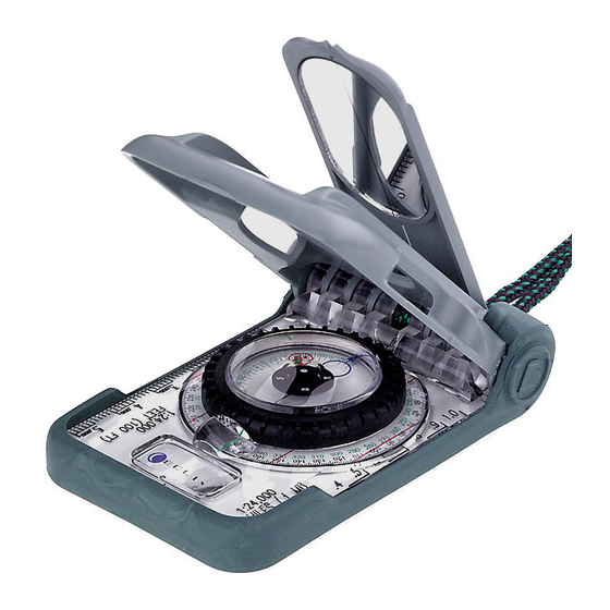
- Page 2 1 – Orientation: Brunton Eclipse 8099 The Eclipse 8099 compass is a sighting instrument which uses the Earth’s magnetic field to display a bearing (direction) in degrees. The Eclipse 8099 also contains three clinometer scales to meas- ure angles from horizontal (0°) to overhead (90°).
- Page 3 1.4 Rotating Azimuth Ring (Figure 1) 1.9 Orienting Circle – BLUE (Figure 2) The rotating azimuth ring includes a graduated dial (described in section 1.7). The blue Printed on the bottom of the vial, the adjustable blue orienting circle is used in bearing and orienting circle and the graduated dial rotate with the rotating azimuth ring.
- Page 4 2 -- Magnetic Declination The isogonic chart shows North America, only. Use an isogonic chart, or a current United States Geological Survey (USGS), Bureau of Land Management (BLM), or another map to determine The Earth is completely surrounded by a magnetic field, and an unobstructed magnetized object magnetic declination at your position.
- Page 5 4. Locate declination scale. 4. Rotate azimuth ring until reflection of blue orienting circle, 5. Grasp black azimuth ring in one hand, and the vial in the other (figure 6). in the mirror, outlines the circled "N". 6. Hold black azimuth ring stationary, and rotate vial until the arrow on the blue orienting circle ·...
- Page 6 4. Position compass at eye level and sight through This is a popular method because it is possible to compare the map to the actual terrain. The Figure 12 the sight hole. following examples use a USGS topographic map. 5. Pivot your body until reflection of the blue orienting circle outlines circled "N"...
- Page 7 The topo-map is now aligned with true north. In the field, it is possible to compare the map to the actual terrain. Now, find the map bearing from one position to another. 6. Place a "point" at a starting position and an "X" at a destination. 7.
- Page 8 Figure 19 · Fill map with additional true north-south lines, spaced approximately 1 inch apart, parallel to map’s margin (figure 19). 5. On the map, mark a start position with a "point" and a destination with an "X". 6. Draw a line connecting both marks.
- Page 9 9. Keeping the clear base stationary on the map, 5. Sight a field bearing to rotate azimuth ring until blue orienting circle landmark ‘1’ – 320° (green points in a northerly direction, and the lines scale), this example. on graduated circle are aligned with the drawn ·...
- Page 10 This section explains positioning on a USGS 7.5 minute, topographic map using Universal Transverse Mercator (UTM) grid (grid coordinate system) and latitude and lon- gitude (spherical coordinate system). The Eclipse 8099 provides Universal Transverse Mercator 000m (UTM) gird scales on the clear base and reference card 6.
- Page 11 10.2 Latitude And Longitude Coordinate System the Eclipse 8099)**. Latitude and longitude scales are not provided with the Eclipse 8099, but determining a position using a latitude and longitude scale, or a ruler is an essential navigation skill. ** Contact Brunton to purchase a latitude- 22' 30"...
- Page 12 10.2.c -- Latitude Determination 11 – Inclination 30" 05' 00" 1. Use the rectangle that completely Inclination is the angular difference from horizontal (0°). The Eclipse 8099 implements three surrounds the ‘X’. clinometer scales, where each is incremented in degrees. The three clinometers are the 5° hinge, 2.
- Page 13 3. At eye-level and arms length, position the compass on its side with the clinometer scale (reference card 1) facing you and down. 4. Sight object behind the compass (figure 36). · Align the side of the compass with the object. 5.
- Page 14 4. Place rubber shoe back on compass. 5. Close cover and open the sight Figure 39 cover to 45°. 6. Position compass at eye-level with mirror extending outward to the left. 7. Above the horizon (level, 0°), sight object through sight hole (figure 39). ·...
- Page 15 · Height = (TanA + TanB) x Distance Before heading into the field, practice using the Eclipse 8099 and a map in a familiar area. Also, carefully re-read the instruction manual to gain a full understanding of Eclipse 8099 applications. ·...
- Page 16 36 - 39 Section 11 – INCLINAISON (charnière, carte et limbe) 40 - 42 Section 12 – CALCUL DE LA HAUTEUR (terrain plat et incliné) 42 - 44 Section 13 – RENSEIGNEMENTS COMPLÉMENTAIRES Section 14 – SPÉCIFICATIONS TECHNIQUES DU MODÈLE ECLIPSE 8099...
- Page 17 1 – ORIENTATION : Brunton Eclipse 8099 La boussole Eclipse 8099 est un instrument de visée qui permet de calculer un relèvement (direc- tion) en degrés par le biais des champs magnétiques de la Terre. Le modèle Eclipse 8099 renferme également trois échelles clinométriques afin de mesurer les angles à...
- Page 18 2 – Déclinaison magnétique Figure 2 - p. 2 Des champs magnétiques ceinturent la Terre. Un objet magnétique sera naturellement orienté vers les pôles magnétiques Nord et Sud. LA déclinaison magnétique (ou variation magnétique) 1.7 Limbe (Figure 2) [1.7 - Graduated Dial] correspond à...
- Page 19 5. Tenez le noire cadran azimutal d’une main et la fiole de l’autre (Figure 6). 3. Placez la boussole à hauteur de la taille et le couvercle de visée pointé vers vous 6. Tout en maintenant le noire cadran azimutal en place, faites pivoter la fiole jusqu’à ce que le (Figure10).
- Page 20 6 – Cartes topographiques 5. Faites pivoter la carte jusqu’à ce que le pointeur bleu en forme de cercle soit superposé au N encerclé rouge. (Fig 16) Une carte topographique est une représentation en deux dimension qui offre un plan tridimension- - La base de la boussole doit demeurer le long de la marge de la carte.
- Page 21 - Remplissez la carte de lignes additionnelles nord-sud en les espaçant d’environ 2,5 cm et les 5. Visez un relèvement vers le point de repère 1, soit 320 (par référence de l’échelle verte) dans disposant de manière parallèle à la marge de la carte (Figure 19). notre exemple.
- Page 22 10 – Positionnement par coordonnées Figure 28 - p. 15 Les récepteurs du système de positionnement global (GPS) sont des outils d’orientation aussi indispensables que les cartes et les boussoles. Le fonctionnement des récepteurs GPS requiert Échelle 1 : 24 000 [Scale: 1:24,000] une compréhension de base des systèmes de coordonnées pour localiser un position.
- Page 23 2. Identifiez et marquez une position sur la carte par un « X ». Grâce aux quadrillages UTM, vous pouvez déterminer votre position avec exactitude à moins 3. Utilisez une échelle de longitude/latitude 1:24 000 afin de déterminer la position en de 100 mètres sans utiliser un rapporteur.
- Page 24 11 - Inclinaison 3. Positionnez la boussole à hauteur d’oeil et le miroir déplié vers l’extérieur et la gauche. L’inclinaison, parfois appelée pente, correspond à la différence angulaire par rapport à l’horizontale 4. Au-dessus ou sous l’horizon, visez un objet à travers la mire (Figure 37). ).
- Page 25 3. Tout en gardant le cadran azimutal immobile, faites pivoter la fiole jusqu’à ce que le 5. Lisez le relèvement en référence de l’échelle noire pour notre exemple). pointeur bleu en forme de cercle soit orienté sur le repère du clinomètre (Figure 38). 6.
- Page 26 * Cette donée inclut le patin de caoutchoiuc et la boussole Eclipse 8099 Sección 12: MEDICIÓN DE ALTURA (Terreno nivelado e inclinado) ......61 - 62 ** Cette donnée inclut le patin de caoutchoiuc, la boussole Eclipse 8099, les fiches de référence et le cordon.
- Page 27 La zapata de caucho desmontable encierra y protege a la brújula y a un conjunto de tarjetas de La brújula Eclipse 8099 es un instrumento de orientación que usa el campo magnético de la Tierra referencia rápida (descritas en 1.11). La zapata de caucho puede también usarse como una goma para mostrar un rumbo (dirección) en grados.
- Page 28 azimut y se usa junto con el círculo de orientación ajustable azul para ajustar la brújula y compen- La mayoría de los mapas usan el norte verdadero como referencia. Cuando el ajuste de la decli- sarla según la declinación magnética. nación magnética se completa, la medición del rumbo que se haga se hará...
- Page 29 Cover Line = Línea de la tapa rojo (Figuras 12 y 13). • No gire el anillo azimutal. Sight Hole = Mirilla 4. Gire el anillo azimutal hasta que la reflexión del círculo de orientación azul en el espejo Figua 12 - p. 8 Figua 13 - p.
- Page 30 Figura 16). parte de abajo del mapa. • En mapas que no sean de USGS o BLM, es posible que el norte verdadero no esté alineado • Trace el resto de las línea del norte verdadero al sur hasta llenar el mapa teniendo en cuen con el margen del mapa, por lo que será...
- Page 31 180°. Otro ejemplo, si observa un rumbo de 320°, el rumbo inverso será 140° (320° - 180° (Figura 27). = 140°). Cuando use la brújula Eclipse 8099 no necesitará añadir ni substraer porque ella tiene Figua 27 - p. 15 dos escalas (Figura 25).
- Page 32 2. Identifique y documente el número de la zona y el datum del mapa (en este ejemplo sería, Las escalas de latitudes y longitudes no vienen con la brújula Eclipse 8099, pero la determinación zona 11 y Datum de América del Norte de 1927).
- Page 33 10.2.c. Determinación de latitud 11 - Inclinación 1. Use el rectángulo donde está encerrada la 'X'. La inclinación es la diferencia angular entre un punto y el plano horizontal (0°). La brújula Eclipseä 2. Coloque la escala verticalmente, hasta que toque dos líneas horizontales de latitud y toque, 8099 tiene tres escalas de medición de inclinación, o clinómetros, que incrementan en grados.
- Page 34 4. Por arriba o por debajo del horizonte, observe un objeto a través de la mirilla (Figura 37). • Alinee la línea de la tapa con la línea de la tapa de observación. • Alinee la línea de la tapa con la línea de la tapa de observación. 8.
- Page 35 45°, para usar las tablas de tangente que se dan en la tarjeta de referencia 8. ciones de la Eclipse 8099. Hágase un experto con el mapa y la brújula y nunca se perderá. Lleve también un equipo de supervivencia y conozca las técnicas de supervivencia.
Need help?
Do you have a question about the Eclipse 8099 and is the answer not in the manual?
Questions and answers