Advertisement
Available languages
Available languages
Quick Links
CONTACT US FIRST
BEFORE MAKING ANY RETURNS TO THE STORE.
sauder.com/service
Visit
Prefer the phone? Give us a ring at
Customer Service is available Monday-Friday - 9 a.m. to 5:30 p.m. EST (except holidays)
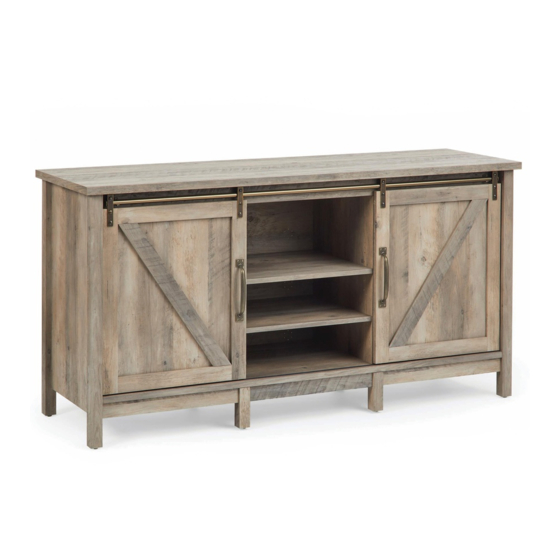
Entertainment Credenza
Model 421192
to order replacement parts, view video assembly tips, or chat with a live rep.
1-800-523-3987
.
Entertaining what
entertains you.
NOTE: THIS INSTRUCTION
BOOKLET CONTAINS IMPORTANT
SAFETY INFORMATION.
PLEASE READ AND KEEP FOR
FUTURE REFERENCE.
English pg 1-36
Français pg 37-40
Español pg 41-44
Lot # 541416
02/19/20
Purchased: __________________
Advertisement

Related Manuals for Bilt Entertainment Credenza 421192


Summary of Contents for Bilt Entertainment Credenza 421192
- Page 1 CONTACT US FIRST BEFORE MAKING ANY RETURNS TO THE STORE. sauder.com/service Visit to order replacement parts, view video assembly tips, or chat with a live rep. 1-800-523-3987 Prefer the phone? Give us a ring at Customer Service is available Monday-Friday - 9 a.m. to 5:30 p.m. EST (except holidays) Entertaining what entertains you.
- Page 2 Table of Contents Assembly Tools Required Part Identifi cation No. 2 Phillips Screwdriver Tip Shown Actual Size Hardware Identifi cation Assembly Steps 6-36 Straight Edge Screwdriver Français 37-40 Español 41-44 Hammer Safety 45-46 Not actual size Warranty WARNING Use of a TV that is too heavy or large is hazardous. A TV that is too heavy will create a risk of a tip-over that can cause severe injury or death.
- Page 3 Now you know Part Identifi cation our ABCs. å While not all parts are labeled, some of the parts will have a label or an inked letter on the edge to help distinguish similar parts from each other. Use this part identifi cation to help identify similar parts. RIGHT END (1) LEFT END (1) UPRIGHT (2)
- Page 4 Hardware Identifi cation å Screws are shown actual size. You may receive extra hardware with your unit. ADJUSTABLE FOOT - 2 HIDDEN CAM - 24 CAM DOWEL - 12 CAM SCREW - 12 PLASTIC 149K WOOD DOWEL - 2 METAL BRACKET - 14 PULL - 2 WASHER - 4 FELT DISC CARD - 2...
- Page 5 Hardware Identifi cation å Screws are shown actual size. You may receive extra hardware with your unit. METAL RUBBER NAIL - 62 HOLE PLUG - 2 APPLIQUE CARD - 2 PIN - 24 SLEEVE - 24 BLACK 9/16" LARGE HEAD SCREW - 36 BROWN 7/16"...
- Page 6 Look for this icon. It means a Step 1 video assembly tip is available at www.sauder.com/service/tips Assemble your unit on a carpeted fl oor or on the empty å carton to avoid scratching your unit or the fl oor. Push eight HIDDEN CAMS (1F) into the UPRIGHTS (C) å...
- Page 7 Step 2 Push four HIDDEN CAMS (1F) into the edges of the ENDS (A and B). Then, å insert the metal end of a CAM DOWEL (2F) into each HIDDEN CAM. Some assembly (and snacks) required. Do not tighten the HIDDEN CAMS in this step. Arrow www.sauder.com/service 421192...
- Page 8 Step 3 Push twelve HIDDEN CAMS (1F) into the edges of the ENDS (A and B) å and SKIRTS (G and H). NOTE: Be sure to use the exact holes shown in the SKIRTS (H). å Do not insert a HIDDEN CAM into this hole.
- Page 9 Step 4 Turn twelve CAM SCREWS (8F) into the LEGS (E and F). å (12 used) www.sauder.com/service 421192 Page 9...
- Page 10 Step 5 Fasten two LEGS (E) to the RIGHT END (A). Tighten four å HIDDEN CAMS. These surfaces should be even. Edge with CAM DOWELS S u r f a c H I D D E N i t h These surfaces should be even.
- Page 11 Step 6 Fasten the remaining LEGS (E) to the LEFT END (B). å Tighten four HIDDEN CAMS. These surfaces should be even. Edge with CAM DOWELS i t h f a c S u r D E N H I D These surfaces should be even.
- Page 12 Step 7 Fasten eight METAL BRACKETS (4G) to the UPRIGHTS (C) å and VALANCE (J). Use eight BLACK 9/16" LARGE HEAD SCREWS (1S). NOTE: Be sure the BRACKETS are even with the edges of å the UPRIGHTS and VALANCE. BLACK 9/16" LARGE HEAD SCREW (8 used in this step) (8 used) Page 12...
- Page 13 Step 8 Fasten the UPRIGHTS (C) to the TOP (N). Tighten four å Caution HIDDEN CAMS. Do not stand the unit upright without the BACK fastened. The unit may collapse. Meet Part (N). This component has been engineered to be lighter, stronger, faster… well ok.
- Page 14 Step 9 Fasten the VALANCE (J) to the UPRIGHTS (C). Use four å BLACK 9/16" LARGE HEAD SCREWS (1S) through the Now might be a METAL BRACKETS on the UPRIGHTS and into the holes good time to refresh in the VALANCE. your drink.
- Page 15 Step 10 Fasten the BOTTOM (I) to the UPRIGHTS (C). Use four å BLACK 1-15/16" FLAT HEAD SCREWS (113S). NOTE: You should start each SCREW a few turns before å completely tightening any of them. 113S BLACK 1-15/16" FLAT HEAD SCREW (4 used in this step) The groove on the other surface of the BOTTOM should be here.
- Page 16 Step 11 Fasten the ENDS (A and B) to the TOP (N). Tighten four å HIDDEN CAMS. Maximum Arrow 210 degrees Fasten the BOTTOM (I) to the ENDS (A and B). Tighten four å HIDDEN CAMS. Minimum Fasten the VALANCE (J) to the ENDS (A and B). Use four å...
- Page 17 Step 12 Insert two WOOD DOWELS (15F) into the holes in the CENTER LEGS (F) as shown in the diagram. å Fasten the SKIRTS (G and H) to the CENTER LEGS (F). Tighten four HIDDEN CAMS. å NOTE: Be sure to position the LEGS and SKIRTS exactly as shown. å...
- Page 18 Step 13 Insert the WOOD DOWELS in the CENTER LEGS (F) å into the holes in the BOTTOM (I). S u r f a c i t h H I D D E N Page 18 421192 www.sauder.com/service...
- Page 19 Step 14 Fasten six METAL BRACKETS (4G) to the SKIRTS (G and H) å and BOTTOM (I). Use twelve BLACK 9/16" LARGE HEAD SCREWS (1S). NOTE: There are no pre-drilled holes in the SKIRTS. The å SCREWS will tighten into the grooves. BLACK 9/16"...
- Page 20 Step 15 Fasten the ADJUSTABLE FEET (34E) to the BOTTOM (I). Use å eight BLACK 9/16" LARGE HEAD SCREWS (1S). NOTE: Adjustments to the ADJUSTABLE FEET will be made å in Step 17 once your unit is standing upright. Peel the FELT DISCS from the FELT DISC CARDS (1M) å...
- Page 21 Step 16 Carefully turn your unit onto its front edges. Unfold the BACK (M) å Caution and lay it over your unit. Do not stand the unit upright without the Make equal margins along the two side edges of the BACK (M). å...
- Page 22 Step 17 Carefully stand your unit upright and position your unit in å its fi nal location. Pro Tip: Lift with your legs. And, you know, Turn the ADJUSTABLE FEET (34E) downward until they å your arms. touch the fl oor. IMPORTANT: The ADJUSTABLE FEET should not extend å...
- Page 23 Step 18 Insert the DOOR TRACK (107M) into the groove in å the BOTTOM (I). NOTE: You may need to gently tap the DOOR TRACK å into the groove in the BOTTOM using your hammer. 107M Groove www.sauder.com/service 421192 Page 23...
- Page 24 Step 19 Insert two HOLE PLUGS (41P) into the holes in å the BOTTOM (I). Page 24 421192 www.sauder.com/service...
- Page 25 Step 20 Push the RUBBER SLEEVES (2R) over the METAL å PINS (1R). Insert the METAL PINS into the hole locations of your choice in the ENDS (A and B) and UPRIGHTS (C). Set the ADJUSTABLE SHELVES (D) onto the METAL PINS. (24 used) www.sauder.com/service 421192...
- Page 26 Step 21 Fasten four DOOR TRACK SUPPORTS (105M) to the å VALANCE (J). Use four BROWN 5/8" FLAT HEAD SCREWS (126S). NOTE: Be sure to position the DOOR TRACK å SUPPORTS exactly as shown. 126S Large hole BROWN 5/8" FLAT HEAD SCREW (4 used in this step) 105M Page 26...
- Page 27 Step 22 Apply TAPE from the TAPE CARDS (4M) to the DOOR å MOLDINGS (K and L) as shown. Then, peel off the backing from the TAPE on the DOOR MOLDINGS. www.sauder.com/service 421192 Page 27...
- Page 28 Step 23 Fasten the DOOR MOLDINGS (K and L) to the DOORS (O and P). å Use four PLASTIC WASHERS (9I) and four BROWN 7/16" LARGE HEAD SCREWS (6S). BROWN 7/16" LARGE HEAD SCREW (4 used in this step) i t h f a c o l e S u r...
- Page 29 Step 24 NOTE: Be sure to separate the LONG BARREL NUTS (152M) å from the BARREL NUTS (109M). Fasten a DOOR WHEEL (98M) to a WHEEL SUPPORT (104M). å Use a LONG BARREL NUT (152M) and a BLACK 5/8" FLAT HEAD SCREW (123S).
- Page 30 Step 25 Fasten two WHEEL SUPPORTS (104M) to the LEFT å DOOR (P). Use four BARREL NUTS (109M) and four 127S BLACK 3/8" MACHINE SCREWS (127S). NOTE: Be sure to position the WHEEL SUPPORTS å BLACK 3/8" MACHINE SCREW exactly as shown. (8 used in this step) Repeat this step for the RIGHT DOOR (O).
- Page 31 Step 26 Fasten two RETAINING BARS (155M) to the LEFT DOOR (P). å Tighten the RETAINING BARS to the DOORS using eight BLACK 5/8" LARGE HEAD SCREWS (140S). 140S NOTE: Be sure to position the RETAINING BARS exactly as shown. å...
- Page 32 Step 27 Fasten two DOOR STOPS (106M) to the DOOR TRACK TUBE (108M). Use two BROWN 1/2" PAN HEAD SCREWS (125S). å NOTE: The SCREWS may turn in hard. Use a little extra force while turning these SCREWS. å Then, hang the DOORS (O and P) onto the center of the DOOR TRACK TUBE (108M) as shown. å...
- Page 33 Step 28 NOTE: A corner of the unit is cut out to show part of the assembly. å Place the DOOR TRACK TUBE (108M) with the DOORS (O and P) onto the å DOOR TRACK SUPPORTS (105M). 105M Carefully pull the bottom of the DOORS (O and P) out at an angle. Then, å...
- Page 34 Step 29 IMPORTANT: The BUMPERS are used to reduce the risk of å fi ngers being pinched when sliding the DOORS. Peel the BUMPERS from the BUMPER CARDS (29M) and å stick the BUMPERS on the upper and lower corners of both sides of each DOOR (O and P).
- Page 35 Step 30 The DOORS may need some side to side adjustments. Follow the å text below to make needed adjustments. NOTE: The spacing between the DOORS and the sides of your unit å should be even from top to bottom. Slide the DOORS over to the sides of your unit.
- Page 36 Step 31 Apply the WARNING LABEL (2L) to the TOP (N). You should be able to read the label when the TV is removed from the å unit. Peel off the backing and apply the label as shown in the diagram. NOTE: This is a permanent label intended to last for the life of the product.
- Page 37 Modèle 421192 Crédence télévision/vidéo/stéréo Utilisez les instructions d’ a ssemblage en français avec les NOUS SOMMES LA POUR VOUS AIDER! schémas étape par étape du manuel d’instruction en anglais. Nous faisons de notre mieux pour nous assurer que votre meuble Chaque étape en français correspond à...
- Page 38 AVERTISSEMENT ÉTAPE 5 L'utilisation d'un téléviseur trop lourd ou trop gros est dangereuse. Un Fixer deux PIEDS (E) à l'EXTRÉMITÉ DROITE (A). Serrer quatre téléviseur trop lourd créera un risque de basculement pouvant provoquer EXCENTRIQUES ESCAMOTABLES. de graves blessures ou la mort. Un téléviseur trop gros pour l'espace disponible risque d'être accidentellement poussé...
- Page 39 ÉTAPE 12 ÉTAPE 17 Insérer deux CHEVILLES EN BOIS (15F) dans les trous des PIEDS Relever, avec précaution, l'élément dans sa position verticale et placer CENTRAUX (F) comme l’indique le schéma. l'élément dans son emplacement fi nal. Fixer les PLINTHES (G et H) aux PIEDS CENTRAUX (F). Serrer quatre Tourner le PIED RÉGLABLE (34E) vers le bas jusqu'à...
- Page 40 ÉTAPE 22 ÉTAPE 27 Fixer deux ARRÊTS DE PORTE (106M) sur le TUBE DE RAIL DE PORTE (108M). Appliquer le RUBAN ADHÉSIF de la CARTE DE RUBAN ADHÉSIF (4M) sur les Utiliser deux VIS TÊTE GOUTTE DE SUIF 13 mm MARRON (125S). MOULURES DE PORTE (K et L) comme l’indique le schéma.
- Page 41 Modelo 421192 Credencia de Entretenimiento Use estas instrucciones de ensamblaje en español junto con las ESTAMOS AQUI PARA AYUDAR! fi guras paso-a-paso provistas en el folleto inglés. Cada paso Tratamos de asegurar que su mueble llega en condición excelente. en español corresponde al mismo paso en inglés. Se destacan Nuestros representantes de Servicio al Cliente son amables y las fi...
- Page 42 ADVERTENCIA PASO 4 El uso de un televisor demasiado pesado o grande es peligroso. Atornille doce BIELAS DE EXCÉNTRICO (8F) dentro de las PATAS (E y F). Un televisor demasiado pesado generará riesgo de caída, lo cual podría causar lesiones graves o muerte. Un televisor demasiado PASO 5 grande para el espacio disponible puede ser empujado o Fije dos PATAS (E) al EXTREMO DERECHO (A).
- Page 43 PASO 12 PASO 17 Inserte dos PASADORES DE MADERA (15F) dentro de los agujeros de las Cuidadosamente ponga la unidad en posición vertical y coloque su PATAS CENTRALES (F), tal como se muestra en el diagrama. unidad en su posición fi nal. Fije los FALDONES (G y H) a las PATAS CENTRALES (F).
- Page 44 PASO 22 PASO 27 (CONTINUACIÓN) Aplique la CINTA de la TARJETA CON CINTA ADHESIVA (4M) a las Luego, cuelgue las PUERTAS (O y P) al centro del TUBO DE CARRIL DE LA MOLDURAS DE PUERTA (K y L) exactamente como se muestra. Luego, PUERTA (108M) como se indica.
- Page 45 WARNING Please use your furniture correctly and safely. Improper use can cause safety hazards, or damage to your furniture or household items. Carefully read the following safety information. Death or serious injury may occur when children climb on audio and/or video equipment furniture. A remote control or toys placed on the furnishing may encourage a child to climb on the furnishing and as a result may tip over onto the child.
- Page 46 ADVERTENCIA Por favor use el mobiliario correcta y seguramente. El mal uso puede causar riesgos de seguridad o daño a las unidades o artículos domésticos. Lea cuidadosamente la siguiente información de seguridad. Pueden suceder lesiones graves o la muerte cuando los niños se suben en los muebles de equipo de audio y/o video. Un control remoto o juguetes colocados en el mueble pueden alentar a un niño a subirse en el mueble y como resultado puede derribarse sobre el niño.
- Page 47 1-YEAR LIMITED WARRANTY 1. Sauder Woodworking Co. (Sauder®) provides limited warranty coverage to the 4. This Warranty applies only to warranted defects that fi rst arise and are reported to original purchaser of this product for a period of one year from the date of purchase Sauder within the warranty coverage period.
- Page 48 If you need assistance 800-523-3987 please contact customer service at Monday-Friday - 9 a.m. to sauder.com/service. 5:30 p.m. EST (except holidays) or at So, how did it go? Register your new product online Set a world record for speed? Feeling good about yourself? For immediate service, 24 hours per day, 7 days per Nice.
Need help?
Do you have a question about the Entertainment Credenza 421192 and is the answer not in the manual?
Questions and answers