National Instruments AT-GPIB Getting Started
Getting started with your device and the ni-488m software for sco unix system v/386
Hide thumbs
Also See for AT-GPIB:
- Getting started (55 pages) ,
- Getting started (53 pages) ,
- Getting started (42 pages)

Related Manuals for National Instruments AT-GPIB


Summary of Contents for National Instruments AT-GPIB
- Page 1 Getting Started with Your AT-GPIB and the NI-488M Software for ™ SCO UNIX System V/386 October 1993 Edition Part Number 320374-01 © Copyright 1991, 1995 National Instruments Corporation. All Rights Reserved.
- Page 2 National Instruments Corporate Headquarters 6504 Bridge Point Parkway Austin, TX 78730-5039 (512) 794-0100 Technical support fax: (800) 328-2203 (512) 794-5678 Branch Offices: Australia (03) 879 9422, Austria (0662) 435986, Belgium 02/757.00.20, Canada (Ontario) (519) 622-9310, Canada (Québec) (514) 694-8521, Denmark 45 76 26 00, Finland (90) 527 2321, France (1) 48 14 24 24,...
- Page 3 The reader should consult National Instruments if errors are suspected. In no event shall National Instruments be liable for any damages arising out of or related to this document or the information contained in it.
- Page 4 National Instruments must be brought within one year after the cause of action accrues. National Instruments shall not be liable for any delay in performance due to causes beyond its reasonable control. The warranty provided herein does not cover damages, defects, malfunctions, or service failures caused by owner's failure to follow the National Instruments installation, operation, or maintenance instructions;...
- Page 5 WARNING REGARDING MEDICAL AND CLINICAL USE OF NATIONAL INSTRUMENTS PRODUCTS National Instruments products are not designed with components and testing intended to ensure a level of reliability suitable for use in treatment and diagnosis of humans. Applications of National Instruments products...
- Page 6 FCC/DOC Radio Frequency Interference Compliance This equipment generates and uses radio frequency energy and, if not installed and used in strict accordance with the instructions in this manual, may cause interference to radio and television reception. This equipment has been tested and found to comply with the following two regulatory agencies: Federal Communications Commission This device complies with Part 15 of the Federal Communications...
- Page 7 Interference Problems. This booklet is available from the U.S. Government Printing Office, Washington, DC 20402, Stock Number 004-000-00345-4. Bescheinigung des Herstellers/Importeurs Hiermit wird bescheinigt, daß die AT-GPIB in Übereinstimmung mit den Bestimmungen der Vfg. 1046/1984 funk entstört ist. Der Detuschen Bundespost wurde das Inverkehrbringen dieses Gerätes angezeigt und die Berechtigung zur Überprüfung der Serie auf...
-
Page 8: Table Of Contents
Step 3. Load the NI-488M Driver ..........3-3 A. Change the Software Settings......... 3-4 DMA Channel..........3-4 Base I/O Address and Interrupt Vector Number ............3-5 B. Install the Driver............. 3-5 Automatic Installation ........3-5 Manual Installation ........3-6 © National Instruments Corp. AT-GPIB for SCO UNIX... - Page 9 Using a Base I/O Address Different from the Software Default Setting ................B-1 Using Interrupt Vector Number 11 or DMA Channel 5..... B-2 Appendix C Hardware Specifications ..............C-1 Appendix D Customer Communication ............D-1 Glossary ....................G-1 AT-GPIB for SCO UNIX © National Instruments Corp.
- Page 10 Tables Table 2-1. Software and Hardware Default Settings and Available Hardware Configurations..........2-2 Table 2-2. Software Default AT-GPIB Base I/O Addresses..... 2-3 Table 2-3. Possible Base I/O Address Switch Settings for the AT-GPIB................2-5 Table 2-4. PC AT I/O Address Map ..........2-7 Table 2-5.
-
Page 11: About This Manual
I/O address, interrupt vector number, and DMA channel software settings. • Appendix C, Hardware Specifications, lists the electrical, environmental, and physical characteristics of the AT-GPIB board and the conditions under which it should be operated. © National Instruments Corp. xiii... -
Page 12: Conventions Used In This Manual
About This Manual • Appendix D, Customer Communication, contains forms you can use to request help from National Instruments or to comment on our products and manuals. • The Glossary contains an alphabetical list and description of terms used in this manual, including abbreviations, acronyms, metric prefixes, mnemonics, and symbols. -
Page 13: Related Documentation
IBM Personal Computer AT Technical Reference Customer Communication National Instruments wants to receive your comments on our products and manuals. We are interested in the applications you develop with our products, and we want to help if you have problems with them. To make it easy for you to contact us, this manual contains comment and configuration forms for you to complete. -
Page 14: Chapter 1 Introduction
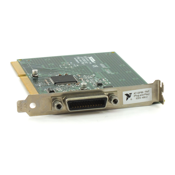
The AT-GPIB is a full-function, high-performance IEEE 488 interface for a 386-based IBM personal computer (herein referred to as the PC AT) that is equipped with 16-bit plug-in slots. The AT-GPIB makes the PC AT a high -performance IEEE 488 Controller. -
Page 15: Hardware Configuration And Installation
This chapter contains step-by-step instructions for configuring and installing the AT-GPIB board in a PC AT. Step 1. Configure the Hardware Figure 2-1 shows the location of the AT-GPIB configuration jumpers and switches. Figure 2-1. AT-GPIB Parts Locator Diagram © National Instruments Corp. -
Page 16: Switch And Jumper Settings
Because SCO UNIX defines the base I/O address, the interrupt line, and the Direct Memory Access (DMA) channel, the hardware settings to which the AT-GPIB board was configured at the factory are not suitable for use under SCO UNIX System V/386. You must change the hardware jumper settings to match the default software configuration settings given in Table 2-1. -
Page 17: Base I/O Address Selection
The base I/O address is determined by the switches at position U25. The switches are set at the factory for the base I/O address 2C0 hex. The AT-GPIB board uses the I/O address space 2C0 through 2DF hex with this setting. If you install more than one AT-GPIB board in your computer, each board must be configured to use a unique base I/O address. -
Page 18: Figure 2-2. Base I/O Address Switch Settings
Switch Set to Hardware Default Setting (Base I/O Address 2C0 hex) ADDRESS Binary Switch Set to Match Software Default Setting (Base I/O Address 260 hex) Figure 2-2. Base I/O Address Switch Settings AT-GPIB for SCO UNIX © National Instruments Corp. -
Page 19: Table 2-3. Possible Base I/O Address Switch Settings For The At-Gpib
Table 2-3 lists the possible switch settings, the corresponding base I/O address, and the I/O address space used for that setting. Table 2-3. Possible Base I/O Address Switch Settings for the AT-GPIB Switch Setting Base I/O Address... -
Page 20: Possible Conflicts
Hardware Configuration and Installation Chapter 2 Table 2-3. Possible Base I/O Address Switch Settings for the AT-GPIB (Continued) Switch Setting Base I/O Address I/O Address Space A9 A8 A7 A6 A5 (hex) Used (hex) 3A0 to 3BF 3C0 to 3DF... -
Page 21: Table 2-4. Pc At I/O Address Map
210 to 213 LIM Expanded Memory Card 219 to 21E Reserved 220 to 23F 240 to 25F AT-GPIB board 1 (software default) LIM Expanded Memory Card LIM Expanded Memory Card 260 to 27F AT-GPIB board 0 (software default) 259 to 267... -
Page 22: Interrupt Selection
The interrupt lines that the AT-GPIB board can use are IRQ3, 4, 5, 6, 7, 9, 10, 11, 12, 14, and 15. If you install more than one AT-GPIB board in your computer, each board must be configured to use a unique AT-GPIB for SCO UNIX ©... -
Page 23: Table 2-5. Software Default At-Gpib Interrupt Request Line
Chapter 2 Hardware Configuration and Installation interrupt request line. The default AT-GPIB board interrupt request levels for the NI-488M software are shown in Table 2-5. You must change the interrupt setting on the hardware to match the software setting. Table 2-5. Software Default AT-GPIB Interrupt Request Line... -
Page 24: Figure 2-3. Interrupt Jumper Settings
Chapter 3, Software Installation and Configuration. Also, make sure that you record the new setting on the AT-GPIB Hardware and Software Configuration Form in Appendix D, Customer Communication. -
Page 25: Possible Conflicts
When they do surface, the problems can exhibit themselves simply as strange behavior. National Instruments has made every effort to select a software default interrupt level that will work. However, because of the numerous different interface boards available for use in the PC AT, it is not possible to select an interrupt level that is guaranteed to work in all systems. - Page 26 Hardware Configuration and Installation Chapter 2 Table 2-6. PC AT Interrupt Assignment Map (Continued) Device AT-GPIB board 1 (software default) PC Network (default) PC Network Alt. (default) Real Time Clock Parallel Port 1 Diskette Controller Fixed Disk and Diskette Drive...
-
Page 27: Dma Channel Selection
The AT-GPIB board is set at the factory to use DMA channel 5 (see Figure 2-1 for the DMA channel location). The DMA channels supported by the AT-GPIB board are channels 5, 6, and 7. If you install more than one AT-GPIB board in your computer, each board must be configured to use a unique DMA channel. -
Page 28: Table 2-8. Dma Channels For The At-Gpib
Hardware Configuration and Installation Chapter 2 Each DMA channel consists of two signal lines as shown in Table 2-8. Table 2-8. DMA Channels for the AT-GPIB Signal Lines Channel Acknowledge Request DACK5 DRQ5 DACK6 DRQ6 DACK7 DRQ7 You must position two jumpers to select a DMA channel. One jumper selects the DMA Request line, and the other selects the DMA Acknowledge line. -
Page 29: Figure 2-4. Dma Channel Jumper Setting
DMA channel setting (DMA channel 7). Jumper Set to Hardware Default Setting (DMA Channel 5) Jumper Set to Match Software Default Setting (DMA Channel 7) Figure 2-4. DMA Channel Jumper Setting © National Instruments Corp. 2-15 AT-GPIB for SCO UNIX... -
Page 30: Figure 2-5. Dma Jumper Setting For No Dma Channel
Hardware Configuration and Installation Chapter 2 If you do not want to use DMA for GPIB transfers (the AT-GPIB board alternatively can use programmed I/O GPIB transfers), you can perform one of the following steps: • Physically disconnect the AT-GPIB board from the DMA channel lines of the PC AT bus by removing the two jumpers. -
Page 31: Table 2-9. Pc At 16-Bit Dma Channel Assignment Map
DMA channel as described in Chapter 3, Software Installation and Configuration . Also, make sure that you record the new setting on the AT-GPIB Hardware and Software Configuration Form in Appendix D, Customer Communication. -
Page 32: Shield Ground Configuration
Chapter 2 Shield Ground Configuration The AT-GPIB board is set at the factory with the jumper in place to connect the logic ground of the AT-GPIB board to its shield ground. This configuration minimizes the EMI emitted from a PC AT equipped with an AT-GPIB board. -
Page 33: Step 2. Install The Hardware
Turn off your computer. Unplug the power cord. Remove the cover. Plug the AT-GPIB board into an unused 16-bit slot (you may have to remove a blank expansion slot cover bracket). Screw the AT-GPIB board mounting bracket to the back panel rail. -
Page 34: Software Installation And Configuration
Install the Link Kit now if you have not already done so. • The AT-GPIB board must already be installed before you install the device driver software. If you have not installed your AT-GPIB board, refer to Chapter 2, Hardware Configuration and Installation, for instructions on how to configure and install your hardware. -
Page 35: Step 2. Install The Ni-488M Software
NI-488M driver for AT-GPIB Driver.o Master file entry for AT-GPIB Master System file entry for AT-GPIB System GPIB device node file for AT-GPIB Node Install script for the handler ibinstall Remove script for the handler ibremove Utility to remove GPIB device nodes ibrmnod Step 2. -
Page 36: Install The Utility Files
Step 3. Load the NI-488M Driver The NI-488M driver supports one or two boards. The first AT-GPIB board is named gpib0 and the second AT-GPIB board is named gpib1 . © National Instruments Corp. -
Page 37: Change The Software Settings
DMA Channel Open the Master file, which contains the following lines: ocrwis ircH ocrwis ircH If you installed only one AT-GPIB board, change only the first line of information. AT-GPIB for SCO UNIX © National Instruments Corp. -
Page 38: Base I/O Address And Interrupt Vector Number
The seventh and eighth fields must be in the range between 0 and 3FF for the AT-GPIB board. The value of the eighth field is obtained by adding 31 decimal or 1F hex to the value of the seventh field. -
Page 39: Manual Installation
Install the driver in the kernel by entering the following command: /etc/conf/bin/idinstall -a ib Create a new UNIX kernel by entering the following command: /etc/conf/bin/idbuild Restart the system to run on the new kernel by entering the following commands: cd / reboot AT-GPIB for SCO UNIX © National Instruments Corp. -
Page 40: Step 4. Configure The Software
If you changed the software settings of the AT-GPIB board, such as the base I/O address, interrupt vector number, or DMA channel, you must make a corresponding change to the parameters shown in ibconf . -
Page 41: System Configuration Information
At system startup, when the NI-488M driver is loaded, the I/O address range, interrupt vector, and DMA level is displayed for device "gpib". This information corresponds to the AT-GPIB board installed as gpib0 in the system. Notice that the interrupt vector number is displayed in octal. So, if you selected interrupt vector 10, it is displayed as 12 in octal. -
Page 42: Removing The Driver
Run ibtsta by typing in the following command: ibtsta If ibtsta completes with no errors and a bus analyzer is available, connect the bus analyzer to the AT-GPIB board, and then run ibtstb by typing in the following command: ibtstb If no error occurs, the NI-488M driver is installed correctly. -
Page 43: Developing Your Application
For more information on creating the GPIB library libgpib.a, refer to the Install the C Library discussion presented previously in this chapter. • For descriptions of the NI-488M functions, refer to the NI-488M Software Reference Manual . AT-GPIB for SCO UNIX 3-10 © National Instruments Corp. -
Page 44: Appendix A New Ni-488M Functions
Appendix A New NI-488M Functions This appendix describes three new NI-488M functions included in the NI-488M software. © National Instruments Corp. AT-GPIB for SCO UNIX... - Page 45 Be sure to return the device descriptor to the pool of available devices by calling ibonl with v=0 when you are finished using the device. If you do not, that device will not be available for the next ibdev call. AT-GPIB for SCO UNIX © National Instruments Corp.
-
Page 46: Ibdev(3
(iberr == EDVR) { /* Bad boardindex or no devices * available. else if (iberr == EARG) { /* The call succeeded, but at least one * pad, sad, tmo, eos, or eot is incorrect. © National Instruments Corp. AT-GPIB for SCO UNIX... -
Page 47: Iblines(3
For iblines to return valid data, a well-behaved IEEE 488 bus must exist. A well-behaved IEEE 488 bus is a bus in which all attached devices are following the IEEE 488 specification. AT-GPIB for SCO UNIX © National Instruments Corp. - Page 48 ((ibsta = iblines (brd0, &clines)) & ERR) error(); if ( !(clines & 0x10)) { printf("GPIB board cannot monitor REN!"); exit(); if (clines & 0x1000) { printf("REN is asserted."); exit(); printf("REN is not asserted."); © National Instruments Corp. AT-GPIB for SCO UNIX...
- Page 49 NO_SAD = 0 ALL_SAD = -1 If ud specifies a device, ibln tests for a Listener on the board associated with the given device. Refer also to IBFIND in the NI-488M Software Reference Manual. AT-GPIB for SCO UNIX © National Instruments Corp.
-
Page 50: Ibln(3
IBLN(3) (continued) IBLN(3) Example Test for a GPIB Listener at pad 2 and sad 0x60 . ibln (ud, 2, 0x60, &listen); if (!listen) { /* No Listener found at this address */ © National Instruments Corp. AT-GPIB for SCO UNIX... -
Page 51: Special Instructions For Changing The Software Settings
NI-488M driver: Decipher the address range of the AT-GPIB board by adding 31 decimal or 1F hex to the base I/O address of the AT-GPIB board. Make a backup copy of the file /etc/conf/pack.d/sio/ space.c. -
Page 52: Using Interrupt Vector Number 11 Or Dma Channel 5
Channel 5 The software default for interrupt vector number is 5 and the software default for DMA channel is 7 for the AT-GPIB board. The default SCO UNIX kernel contains the Adaptec SCSI driver, which uses interrupt vector number 11 and DMA channel 5. If you are not using an Adaptec SCSI... - Page 53 9. Relink the kernel by changing to the directory /etc/conf/cf.d and entering the following command: ./link_unix Answer yes to all questions. 10. Reboot the system to run on the new kernel by entering the following commands: cd / reboot © National Instruments Corp. AT-GPIB for SCO UNIX...
-
Page 54: Hardware Specifications
Appendix C Hardware Specifications This appendix lists the electrical, environmental, and physical characteristics of the AT-GPIB board and the conditions under which it should be operated. Table C-1. Electrical Characteristics Characteristic Specification Maximum GPIB Transfer Rate 1.4 Mbytes/s* Power Requirement +5 VDC 0.66 A Typical... -
Page 55: Customer Communication
Filling out a copy of the Technical Support Form before contacting National Instruments helps us help you better and faster. National Instruments provides comprehensive technical assistance around the world. - Page 56 National Instruments for technical support helps our applications engineers answer your questions more efficiently. If you are using any National Instruments hardware or software products related to this problem, include the configuration forms from their user manuals. Include additional pages if necessary.
- Page 57 National Instruments software product Version Configuration The problem is List any error messages The following steps will reproduce the problem...
- Page 58 Interrupt Address Line Channel 1st AT-GPIB 2nd AT-GPIB Software • NI-488M Software Version Number on Distribution Disk (Disk Label: NI-488M Distribution Disk AT-GPIB SCO UNIX System V/386 Handler and C Interface) • Software Settings Base I/O Interrupt Address Vector Channel...
- Page 59 Other Products • SCO UNIX System V/386 Version • Computer Make and Model • Microprocessor • Clock Frequency • Type of Video Board Installed • Type of other boards installed and their respective hardware settings Base I/O Interrupt Board Type Address Level Channel...
- Page 60 National Instruments encourages you to comment on the documentation supplied with our products. This information helps us provide quality products to meet your needs. ™ Title: Getting Started with Your AT-GPIB and the NI -488M Software for SCO UNIX System V/386 Edition Date: October 1993 Part Number:...
- Page 61 Thank you for your help. Name Title Company Address Phone Mail to: Technical Publications National Instruments Corporation 6504 Bridge Point Parkway, MS 53-02 Austin, TX 78730-5039 Fax to: Technical Publications National Instruments Corporation MS 53-02 (512) 794-5678...
-
Page 62: Glossary
Interrupt Request meters megabytes of memory NDAC Not Data Accepted Bit NRFD Not Ready For Data Bit Remote Enable SCSI Small Computer System Interface seconds Service Request volts direct current video graphics array © National Instruments Corp. AT-GPIB for SCO UNIX...
Need help?
Do you have a question about the AT-GPIB and is the answer not in the manual?
Questions and answers