
Related Manuals for Grundfos Hydro 50-250/263 YJS ASD-U3-B


Summary of Contents for Grundfos Hydro 50-250/263 YJS ASD-U3-B
- Page 1 GRUNDFOS INSTRUCTIONS Hydro EN Grundfos firefighting systems Installation and operating instructions Hydro EN Installation and operating instructions (all available languages) http://net.grundfos.com/qr/i/99901851...
- Page 3 Hydro EN English (GB) Installation and operating instructions ............4 Български...
-
Page 4: Table Of Contents
General safety warnings ..... . 5 The symbols and hazard statements below may appear in Grundfos installation and operating instructions, safety instructions and Product introduction. -
Page 5: Target Group
1.3 Target group DANGER Trapping hazard These installation and operating instructions are intended for Death or serious personal injury professional installers and for the operators of the product. ‐ Make sure that you wear suitable clothing on site. Do We recommend that installation is carried out by skilled persons not wear loose or frayed clothing, long free hair or with technical qualifications required by the specific legislation in jewellry to avoid being trapped into the equipment. -
Page 6: Product Introduction
The fire pump set can only be stopped manually under automatic Jockey pump operation mode via a dedicated key removable from the control A jockey electric pump (always included), operated by a dedicated panel. Due to the regulation for fire and the active protection of the control panel, automatically guarantees system pressurization in pumping system, it is required not to have any emergency stop. -
Page 7: Identification
Electric pump: 3x400V / 50Hz 1x220V / 50Hz Diesel pump: (*) Control panel main supply Made in Italy Grundfos Pompe Italia S.r.l., 20060 Truccazzano, Italy Example of nameplate The following diagram shows the location of the nameplates. Pos. Description Nameplates... - Page 8 The following nameplates and labels can also be found: • pump nameplate (one per pump placed on the bearings bracket) • the nameplate of each electric motor or diesel engine (placed on the motor or engine) • control panel label (one per each control panel placed on the side of the panel or the inner side of the front door, depending on the model). 2.2.2 Type key Example Hydro EN...
-
Page 9: Receiving The Product
3. Receiving the product 3.4 Handling and lifting the product 3.1 Inspecting the product Before starting operation, read carefully all documentation and manuals delivered together with the fire pump set. On receipt of the product, do the following: 1. Make sure that the pump set corresponds to the order and that accessories, if any, are not missing. -
Page 10: Installation Requirements
4. Installation requirements Refer to the system design for the information of the room installation, specifically for the construction works, ventilation, air exchange, power supply system and the evacuation of the exhaust gases of the diesel engine. The installation must be carried out timely by specialists appointed by the client in compliance with relevant regulations and provisions. -
Page 11: Diesel Pumps With Direct Air Cooling
The pictures below give an indication of the minimum free space 4.3 Diesel pumps with water/water heat exchanger to be left around the pump set. WARNING Hot surface Death or serious personal injury ‐ Open the coolant tank cap only when the engine is cold and only if strictly necessary. - Page 12 The heat exchanger circuit is connected to the pump outlet just Most of the heat is dissipated by the described cooling before the check valve with a pipe of appropriate size. system. Despite this, the running engine emits a certain amount of energy in the form of heat into its environment.
-
Page 13: Diesel Tank Withcontainmentbasin Andventconnection
4.4 Diesel tank with containment basin Use appropriate lifting techniques and do not bend the and vent connection waist. CAUTION Toxic material Only use suitable fuel (refer to the engine manual). The Minor or moderate personal injury unsuitable fuel can ignite flames and/or cause serious ‐... -
Page 14: Exhaust Gas Outlet Of The Diesel Pumps
4.5 Exhaust gas outlet of the diesel pumps 4.6 Exhaust back pressure WARNING Wrong sizing of the exhaust pipe can affect correct Toxic material operation of the pump set. Death or serious personal injury ‐ All connections must be perfectly sealed in order to As previously stated, the exhaust gases must be discharged from avoid gas leakage inside the technical room. -
Page 15: Mechanical Installation
5. Mechanical installation The design and execution of the supports of the pump set must be properly carried out in accordance with the WARNING relevant standards and regulations by specialists Crushing of hands commissioned by the client. Death or serious personal injury ‐... -
Page 16: Foundationandanchorage
5.1 Foundation and anchorage 6. Electrical installation The anchoring system must guarantee the stability and WARNING alignment of the fire pump set over time and have Electric shock mechanical characteristics such as withstanding static Death or serious personal injury and dynamic loads, as well as vibrations of the unit during ‐... -
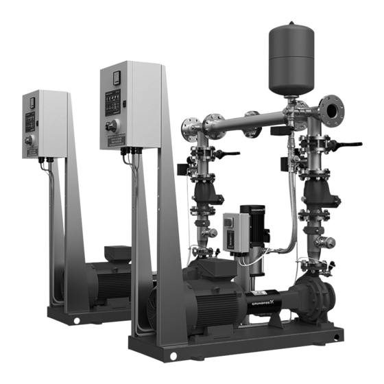
Page 17: Functional Diagram
7. Functional diagram Functional diagram Symbol Description Pos. Connection/description Butterfly valve Independent inlet connection for the duty electric pump Concentric divergent Independent inlet connection for the standby diesel pump Inlet connection for the jockey pump Eccentric divergent Recirculation circuit connection for the duty or standby electric pump Grooved coupling Recirculation circuit connection for the duty or... -
Page 18: Startup
8. Startup 8.1 Alignment of the pumps 8.1.1 Alignment of duty electric pumps Before starting any type of operation, carefully read the contents of this installation and operating instructions DANGER and the accompanying documentation. Automatic startup Death or serious personal injury WARNING ‐... -
Page 19: Priming The Pumps
8.1.2 Coupling of duty diesel pumps 8.2 Priming the pumps DANGER Automatic startup Before starting the priming operations, read Death or serious personal injury the installation and operation instructions. ‐ The fire pump set can start up automatically at any time. -
Page 20: Control Functions
9. Control functions 9.1.1.1 Operating modes of jockey pump Manual operating mode 9.1 Control panel Start the pump manually by pressing and 9.1.1 Control panel for the jockey pump holding the START button. The pump stops once the START button is released. - Page 21 9.1.1.4 Jockey pump protection against dry-running Factory LED (mode) Alarm effect Reset The jockey pump control box is designed for dry-running protection. setting This function is disabled at the factory. The factory setting is DRY% Thermal overload trimmer set on value zero and physical jumper on the terminal Alarm condition: the motor current is higher than the set value board.
- Page 22 9.1.2 Control panel for the duty electric pump Factory LED (mode) Alarm effect Reset setting The duty electric pumps are controlled by an independent control panel which provides easy reading of the measurement instruments Prolonged operation and signals from a single observation point. Alarm condition: the pump runs continuously for more than 8 The starting of the electric motors is available as standard in the hours.
- Page 23 The user interface of the EPC 300 control unit (D) shows the 9.1.2.3 Testing the pressure switches for electric pump following signal lights and operating buttons: Two pressure switches for each main pump are required on the fire- fighting main pump sets, as specified in the EN 12845 standard. The operation of every single pressure switch must be checked regularly, and for this reason the control panels are equipped with a Manual START button...
- Page 24 9.1.2.5 Automatic stop function for electric pump 9.1.2.6 Signalling outputs (potential-free contacts) for duty electric pump In some countries and for specific applications, it is allowed for the duty pump to stop automatically. The outputs listed below in accordance with the EN 12845 standard are provided for supervising the pump set from a control room: When this function is enabled, the duty pump stops automatically when the pressure in the system exceeds the stop threshold of the...
- Page 25 9.1.3 Control panel for the duty diesel pump The user interface has a backlit LCD display, so you can read it even when the room lighting is poor. By means of the light signals, The duty diesel pump is controlled by an independent control panel the pump set status is always under control.
- Page 26 9.1.3.1 Functions of buttons on the LCD display 9.1.3.2 Manual operating mode of diesel pump The following buttons can be found on the LCD multifunction 1. Set the key selector to TEST. display of the control panel: 2. Start the engine by pressing the engine START button. 3.
- Page 27 9.1.3.5 Testing the pressure switches for diesel pump 9.1.3.8 Automatic stop function for diesel pump In some countries and for specific applications, it is allowed for Two pressure switches for each main pump are required on the duty pump to stop automatically. the firefighting main pump sets, as specified in the EN When this function is enabled, the duty pump stops automatically 12845 standard.
- Page 28 9.1.3.11 Freely accessible parameters 9.1.3.12 Password-protected parameters The password-protected parameters are only available to authorised persons. Parameter Description Italian, English, French, German, Spanish, Parameter Description Portuguese, Czech, Polish, Hungarian, Language Slovak, Swedish, Finnish, Danish, For selecting the battery voltage (12 or 24 Battery voltage Norwegian, Dutch, Serbo, Romanian, Turkish...
- Page 29 9.1.3.13 Calibrating the engine speed 9.1.3.15 Alarms As required in the EN 12845 standard, the duty Under no circumstances should the fire pump set be pump cannot be stopped by any alarm. The duty pump operated, when the belt guard is not in place and suitably can only be stopped manually unless in applications with secured.
-
Page 30: Operating Modes
Each pump installed in the system, regardless of jockey or duty The control panel of the diesel pump can be connected with remote pump either driven by electricity or diesel, is operated and devices such as, for example, the Grundfos remote acoustic-visual controlled through a dedicated control panel. alarm. -
Page 31: Service
10. Service 10.2 Verifications and checks WARNING 10.1 Maintenance Electric shock Death or serious personal injury Before starting any operation, read carefully all the ‐ The fire pump set can start up automatically at any documentation and manuals delivered together with the time. - Page 32 10.2.2 Duty diesel pump 10.2.2.4 Checking the water flow in the heat exchanger 1. Through the pressure gauge located upstream of the Check if all the screws are in place and correctly exchanger, make sure that during operation of the diesel tightened on a regular basis.
-
Page 33: Storage
The pump set must be stored in a frost-free The Grundfos dedicated kit (optional) includes a shut-off room protected from direct exposure to the environment. valve, a flowmeter and a control valve. The configuration and... -
Page 34: Fault Finding
12.3 The thermal relay trips (only for jockey pumps) Cause Remedy Too much energy consumption • Replace the motor. Contact due to defective motor winding. Grundfos Service. The pump is under strain. • Dismantle and clean the pump. -
Page 35: Technical Data
This product or parts of it must be disposed of in an environmentally sound way. 1. Use the public or private waste collection service. 2. If this is not possible, contact the nearest Grundfos company or service workshop. The crossed-out wheelie bin symbol on a product means that it must be disposed of separately from household waste. - Page 36 Standard used: Panel - EN 60439-2:2011. • Electromagnetic compatibility (EMC) Directive (2014/30/EU). This EC/EU declaration of conformity is only valid when published as part of the Grundfos installation and operating instructions (publication number 99901851). Bjerringbro, 19 March 2021 Joachim Krogshave...
- Page 37 Tel.: +387 33 592 480 Centre Turkey Fax: +387 33 590 465 29-33 Wing Hong Street & 68 King Lam GRUNDFOS Pumper A/S GRUNDFOS POMPA San. ve Tic. Ltd. Sti. www.ba.grundfos.com Street, Cheung Sha Wan Strømsveien 344 Gebze Organize Sanayi Bölgesi E-mail: grundfos@bih.net.ba...
- Page 38 99901851 06.2021 ECM: 1316489...
Need help?
Do you have a question about the Hydro 50-250/263 YJS ASD-U3-B and is the answer not in the manual?
Questions and answers