Terex Genie QS-12R Operator's Manual
Hide thumbs
Also See for Genie QS-12R:
- Service manual (155 pages) ,
- Service manual (155 pages) ,
- Service manual (154 pages)

Related Manuals for Terex Genie QS-12R


Summary of Contents for Terex Genie QS-12R
- Page 1 Operator's Manual Serial Number Range -12R ™ from QSP-6000 Australia -15R ™ -20R ™ with Maintenance Information Second Edition First Printing Part No. 1297730GT...
-
Page 2: Table Of Contents
Specifications ............52 Copyright © 2011 Terex Corporation Second Edition: First Printing, September 2020 Genie is a registered trademark of Terex South Dakota, Inc. in the U.S.A. and many other countries. “QS” is a trademark of Terex South Dakota, Inc. -
Page 3: Introduction
Second Edition • First Printing Operator's Manual Introduction Introduction About this manual Intended Use and Familiarization Guide Genie appreciates your choice of our machine for your application. Our number one priority is user The intended use of this machine is to lift safety, which is best achieved by our joint efforts. - Page 4 Operator's Manual Second Edition • First Printing Introduction Platform controls symbology and related Ground controls symbology and related machine movement: machine movement: Lift function enable button Lift function enable button Drive function enable button Platform up/down button Platform up/down (when lift function selected) Sequential functions and movement: Drive forward/reverse (when drive function...
- Page 5 Second Edition • First Printing Operator's Manual Introduction Bulletin Distribution and Compliance Contacting the Manufacturer Safety of product users is of paramount At times it may be necessary to contact Genie. importance to Genie. Various bulletins are used by When you do, be ready to supply the model Genie to communicate important safety and number and serial number of your machine, along product information to dealers and machine...
- Page 6 Operator's Manual Second Edition • First Printing Introduction Danger Failure to obey the instructions and safety rules in this manual will result in death or serious injury. Do Not Operate Unless: You learn and practice the principles of safe machine operation contained in this operator’s manual.
- Page 7 Second Edition • First Printing Operator's Manual Introduction Safety Sign Maintenance Replace any missing or damaged safety signs. Keep operator safety in mind at all times. Use mild soap and water to clean safety signs. Do not use solvent-based cleaners because they may damage the safety sign material.
-
Page 8: Symbol And Hazard Pictorials Definitions
Operator's Manual Second Edition • First Printing Symbol and Hazard Pictorials Definitions Symbol and Hazard Pictorials Definitions Read the operator’s Read the service Crush hazard No smoking Collision hazard manual manual Collision hazard Tip-over hazard Tip-over hazard Electrocution hazard Electrocution hazard Burn hazard Explosion hazard Fire hazard... - Page 9 Second Edition • First Printing Operator's Manual Symbol and Hazard Pictorials Definitions Maintain required Access by trained Chock the wheels Release brakes Grounded AC clearance and authorized 3-wire only personnel only Replace damaged Lanyard anchorage Wheel load Side force Manual force wires and cords points Lifting point...
-
Page 10: General Safety
Operator's Manual Second Edition • First Printing General Safety General Safety ™ ™ ™ -R12 • QS -R15 • QS -R20 Part No. 1297730GT... - Page 11 Second Edition • First Printing Operator's Manual General Safety These decals are model, option or configuration specific. ™ ™ ™ Part No. 1297730GT -R12 • QS -R15 • QS -R20...
-
Page 12: Personal Safety
Operator's Manual Second Edition • First Printing Personal Safety Personal Safety Personal Fall Protection Personal fall protection equipment (PFPE) is not required when operating this machine. If PFPE is required by job site or employer rules, the following shall apply: All PFPE must comply with applicable governmental regulations and must be inspected and used in accordance with the manufacturer’s... -
Page 13: Work Area Safety
Second Edition • First Printing Operator's Manual Work Area Safety Work Area Safety Electrocution Hazards Tip-over Hazards Occupants, equipment and materials must not This machine is not exceed the maximum platform capacity. Weight in electrically insulated and will trays and in each bike rack is part of the total not provide protection from platform load. - Page 14 Operator's Manual Second Edition • First Printing Work Area Safety Do not raise the platform Do not operate the machine unless the machine is on a in strong or gusty winds. Do firm, level surface. not increase the surface area of the platform or the load.
- Page 15 Second Edition • First Printing Operator's Manual Work Area Safety Do not use the platform controls to free a platform Do not modify or alter a mobile elevating work that is caught, snagged, or otherwise prevented platform without prior written permission from the from normal motion by an adjacent structure.
- Page 16 Operator's Manual Second Edition • First Printing Work Area Safety Crushing Hazard Fall Hazards Keep hands and limbs out of mast. The guard rail system provides fall protection. If occupant(s) of the platform are required to wear Do not work under the platform or mast without the personal fall protection equipment (PFPE) due to battery cover raised.
- Page 17 Second Edition • First Printing Operator's Manual Work Area Safety Collision Hazards Do not lower the platform unless the area below is Be aware of limited sight clear of personnel and distance and blind spots obstructions. when driving or operating. Be aware of extended platform position when moving the machine.
- Page 18 Operator's Manual Second Edition • First Printing Work Area Safety Bodily Injury Hazard Damaged Machine Hazards Do not operate the machine with a hydraulic oil or Do not use a damaged or malfunctioning machine. air leak. An air leak or hydraulic leak can penetrate Conduct a thorough pre-operation inspection of the and/or burn skin.
- Page 19 Second Edition • First Printing Operator's Manual Work Area Safety Battery Safety Component Damage Hazard Do not use any battery charger greater than 24V to Burn Hazards charge the batteries. Batteries contain acid. Electrocution/Burn Hazards Always wear protective clothing and eye wear when Connect the battery charger to a working with batteries.
-
Page 20: Legend
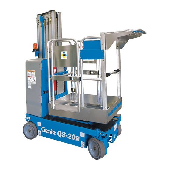
Operator's Manual Second Edition • First Printing Legend Legend Legend Pothole guard Hydraulic oil level indicator 16 Tool Tray Non-steer tire 10 Mast 17 Steer tire Forklift pockets 11 Brake release pump knob 18 GFCI outlet (under covers) Transport tie-down 19 Obstruction sensing pad 12 Platform controls Emergency lowering valve... -
Page 21: Controls
Second Edition • First Printing Operator's Manual Controls Controls The ground control station is to be used as a means to raise the platform for function tests and for storage purposes. The ground control station can be used in the event of an emergency to rescue an incapacitated person in the platform. - Page 22 Operator's Manual Second Edition • First Printing Controls 1283810 A 1283810 A Platform Control Panel Proportional control handle and function Red Emergency Stop button enable switch for drive, steer, and lift functions Push in the red Emergency Stop button to the Lift function: Press and hold the function off position to stop all functions.
- Page 23 Second Edition • First Printing Operator's Manual Controls Thumb rocker switch for steer function Press the left side of the thumb rocker and the machine will turn in the direction the blue triangle points on the platform control panel. Press the right side of the thumb rocker and the machine will turn in the direction the yellow triangle points on the platform control...
-
Page 24: Inspections
Operator's Manual Second Edition • First Printing Inspections Inspections Pre-operation Inspection Fundamentals It is the responsibility of the operator to perform a pre-operation inspection and routine maintenance. The pre-operation inspection is a visual inspection performed by the operator prior to each work shift. Do Not Operate Unless: The inspection is designed to discover if anything is apparently wrong with a machine before the... - Page 25 Second Edition • First Printing Operator's Manual Inspections Pre-operation Inspection Pothole guards Lanyard anchorage points Be sure that the operator’s, safety, and Work trays and bike racks (if equipped) responsibilities manuals are complete, legible and in the storage container located in the ...
- Page 26 Operator's Manual Second Edition • First Printing Inspections Function Test Fundamentals The function tests are designed to discover any malfunctions before the machine is put into service. The operator must follow the step-by-step instructions to test all machine functions. A malfunctioning machine must never be used. If malfunctions are discovered, the machine must be Do Not Operate Unless: tagged and removed from service.
- Page 27 Second Edition • First Printing Operator's Manual Inspections At the Ground Controls Test the Up/Down Functions The audible warnings on this machine and the Select a test area that is firm, level and free of standard horn all come from the same central hazards.
- Page 28 Operator's Manual Second Edition • First Printing Inspections Test Auxiliary Lowering Test the Function Enable Switch and the Up/Down Functions 18 Activate the up function by pressing the lift enable button and platform up button, and 25 Press the outdoor use button. raise the platform approximately 2 ft.
- Page 29 Second Edition • First Printing Operator's Manual Inspections Test the Steering Test the Outdoor Use Button Note: When performing the steer and drive 35 Do not press and hold the function enable function tests, stand in the platform facing the steer switch on control handle.
- Page 30 Operator's Manual Second Edition • First Printing Inspections Test Drive and Braking Test Drive Tilt Cutout Note: Perform this test from the ground with the 45 Press the drive function button. platform controller. Do not stand in the platform. 49 Fully lower the platform. 46 Press and hold the function enable switch on 50 Drive the machine onto a slope where the the control handle.
- Page 31 Second Edition • First Printing Operator's Manual Inspections 57 Return to level ground and raise the platform 65 Fully lower the platform. in excess of approximately 7 ft/2.13 m. 66 Drive the machine. 58 Drive the machine onto a slope where the Result: The machine should drive.
- Page 32 Operator's Manual Second Edition • First Printing Inspections Test the Pothole Guards 78 Press the drive function button. Note: The pothole guards should automatically deploy when the platform is raised. The pothole 79 Press and hold the function enable switch on guards activate limit switches that allow the the control handle.
- Page 33 Second Edition • First Printing Operator's Manual Inspections Workplace Inspection Checklist Be aware of and avoid the following hazardous situations: drop-offs or holes bumps, floor obstructions, or debris sloped surfaces Do Not Operate Unless: unstable or slippery surfaces ...
- Page 34 Operator's Manual Second Edition • First Printing Inspections Inspection for Decals with Words Part No. Decal Description *133450 Instructions – Work Tray Determine whether the decals on your machine 133451 Danger – Max Capacity, 45 lbs / 20 kg, have words or symbols. Use the appropriate Bike Racks* inspection to verify that all decals are legible and in 133505...
- Page 35 Second Edition • First Printing Operator's Manual Inspections ™ ™ ™ Part No. 1297730GT -R12 • QS -R15 • QS -R20...
-
Page 36: Operating Instructions
Operator's Manual Second Edition • First Printing Operating Instructions Operating Instructions Fundamentals The Operating Instructions section provides instructions for each aspect of machine operation. It is the operator’s responsibility to follow all the safety rules and instructions in the operator’s, safety, and responsibilities manuals. - Page 37 Second Edition • First Printing Operator's Manual Operating Instructions Emergency Stop Operation from Platform Push in the red Emergency Stop button to the off Be sure the battery pack is connected before position at the ground controls or the platform operating the machine.
- Page 38 Operator's Manual Second Edition • First Printing Operating Instructions Use the color-coded direction arrows on the To Steer platform controls and on the platform to identify the Press the drive function button. On the LED direction the machine will travel. screen, a circle below the drive function Machine travel speed is restricted when the symbol will turn on.
- Page 39 Second Edition • First Printing Operator's Manual Operating Instructions Lay the piece of wood on the slope. Driving on a slope Determine the slope and side slope ratings for the At the downhill end, lay the level on the top edge of machine and determine the slope grade.
- Page 40 Operator's Manual Second Edition • First Printing Operating Instructions Operational indicator codes Platform Overload If the platform controls LED or ground controls If the platform controls LED diagnostic readout LCD diagnostic readout displays an operational displays a flashing OL and the ground controls indicator code such as LL, the fault condition must LCD diagnostic readout displays OL: Platform repaired or removed before resuming machine...
- Page 41 Second Edition • First Printing Operator's Manual Operating Instructions Tilt Sensor Activation Settings Battery Level Indicator Chassis Angle (side to side) 1.5° Use the LED diagnostic readout to determine the battery level. 3° Chassis Angle (front to back) If the tilt alarm sounds while Note: When a blinking LO code appears on the raising the platform, lower the platform controls LED display, the machine must...
- Page 42 Operator's Manual Second Edition • First Printing Operating Instructions To lower the work tray: Operating Obstruction Sensing System Pull the snap pin while vertically raising the tray to clear the work tray mount. A sounding alarm indicates that an obstruction or a Lower the work tray to the stowed position.
- Page 43 Second Edition • First Printing Operator's Manual Operating Instructions Adjustable Work Tray Operation When the desired height is reached, use the lower handle to fully rotate the tray to a horizontal position. Engage the support bar To adjust the work tray: with the rail teeth.
- Page 44 Operator's Manual Second Edition • First Printing Operating Instructions Lift Tools Work Tray Instructions To stow the work tray: Grasp the lower handle of the adjustable work The Lift Tools Work Tray assembly consists of one tray with one hand. tray and a mounting bracket with hardware.
- Page 45 Second Edition • First Printing Operator's Manual Operating Instructions Observe and Obey: Lift Tools After Each Use Work Tray Installation Select a safe parking location—firm level surface, clear of obstruction and traffic. Lift Tools Work Tray must be installed on the inside of the platform.
- Page 46 Operator's Manual Second Edition • First Printing Operating Instructions Standard Batteries Remove the battery vent caps and check the battery acid level. If necessary, add only enough distilled water to cover the plates. Do not overfill prior to the charge cycle. Replace the battery vent caps.
-
Page 47: Transport And Lifting Instructions
Second Edition • First Printing Operator's Manual Transport and Lifting Instructions Transport and Lifting Instructions The machine must be on a level surface or secured before releasing the brakes. Do not drive the machine on a slope that exceeds the uphill, downhill or side slope rating. - Page 48 Operator's Manual Second Edition • First Printing Transport and Lifting Instructions After the machine is loaded: Brake Release Operation Chock the wheels to prevent the machine from Chock the wheels to rolling. prevent the machine from Pull out the red Emergency Stop button at both rolling.
- Page 49 Second Edition • First Printing Operator's Manual Transport and Lifting Instructions Securing to Truck or Trailer for Inspect the entire machine for loose or unsecured items. Transit Use the tie-down points on the chassis for Always use the extension deck lock when the anchoring down to the transport surface.
- Page 50 Operator's Manual Second Edition • First Printing Transport and Lifting Instructions Lifting the Machine with a Forklift Be sure the extension deck, controls and component trays are secure. Remove all loose items on the machine. Fully lower the platform. The platform must remain lowered during all loading and transport Observe and Obey: procedures.
- Page 51 Second Edition • First Printing Operator's Manual Transport and Lifting Instructions Loading the Machine With a Crane Fully lower the platform. Be sure the extension deck, controls and component trays are secure. Remove all loose items on the machine. Use the lifting eye mounted on the rear mast column.
-
Page 52: Maintenance
Operator's Manual Second Edition • First Printing Maintenance Maintenance Check the Hydraulic Oil Level Maintaining the hydraulic oil at the proper level is essential to machine operation. Improper hydraulic oil levels can damage hydraulic components. Daily Observe and Obey: checks allow the inspector to identify changes in oil level that might indicate the presence of hydraulic ... - Page 53 Second Edition • First Printing Operator's Manual Maintenance Check the Batteries Scheduled Maintenance Maintenance performed quarterly, annually and every two years must be completed by a person trained and qualified to perform maintenance on Proper battery condition is essential to good this machine according to the procedures found in machine performance and operational safety.
-
Page 54: Specifications
Operator's Manual Second Edition • First Printing Specifications Specifications Model QS-12R Airborne noise emissions Height, working maximum indoor 17 ft 4 in 5.3 m Sound pressure level at ground <70 dBA workstation Height, working maximum 15 ft 1 in 4.60 m outdoor Sound pressure level at platform <70 dBA... - Page 55 Second Edition • First Printing Operator's Manual Specifications Model QS-15R Airborne noise emissions Height, working 20 ft 8 in 6.3 m Sound pressure level at ground workstation <70 dBA maximum indoor Sound pressure level at platform workstation <70 dBA Height, working 17 ft 1 in 5.2 m Vibration value does not exceed 2.5 m/s...
- Page 56 Operator's Manual Second Edition • First Printing Specifications Model QS-20R Airborne noise emissions Height, working maximum 25 ft 9 in 7.9 m Sound pressure level at ground workstation <70 dBA indoor Sound pressure level at platform workstation <70 dBA Height, working maximum 21 ft 6 in 6.6 m Vibration value does not exceed 2.5 m/s...
Need help?
Do you have a question about the Genie QS-12R and is the answer not in the manual?
Questions and answers