Table of Contents
Advertisement
Advertisement
Table of Contents

Related Manuals for Ortur Laser Master 2 Pro


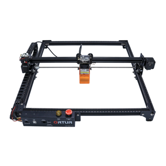
Summary of Contents for Ortur Laser Master 2 Pro
- Page 1 Dongguan Ortur Intelligent Technologies Co., Ltd. https://ortur.tech/olm2pro Laser Master 2 Pro Optional Upgrades Offline Controller Manual Z-Height User Manual V1.0 - 01 June 2021 No.1 Building, Ruijin Science and Technology Industrial Park, Changping, Dongguan 523558, Guandong Province, China...
- Page 2 Dongguan Ortur Intelligent Technologies Co., Ltd. https://ortur.tech/olm2pro Welcome Thank you for choosing the Ortur Laser Master 2 Pro! This manual will guide you through the steps required to assemble, fine tune and operate your Ortur Laser Master 2 Pro safely and productively.
- Page 3 Dongguan Ortur Intelligent Technologies Co., Ltd. https://ortur.tech/olm2pro Contents No.1 Building, Ruijin Science and Technology Industrial Park, Changping, Dongguan 523558, Guandong Province, China...
-
Page 4: Basic Information
Security & Safety Guidelines Basic Information The Ortur Laser Master 2 Pro engraves and cuts materials by the means of a high-energy diode laser beam. The hazards associated with a high-energy diode laser beam include the possibility of fires, generation of hazardous and/or irritating toxic fumes, but more importantly damage to eyes and skin. -
Page 5: Hazards And Precautions
Improper use of the controls and modification of the safety features may cause serious eye injury and burns. It is recommended to select a room to operate the Ortur Laser Master 2 Pro where access can be controlled by means of a solid door. No direct view to the laser beam should be possible from the outside. - Page 6 The sensor can only alert the user for the possibility of a flame on the machine. Do not ignore the Flame sensor Alarm! It is recommended to select a room to operate the Ortur Laser Master 2 Pro where access to good ventilation is available as well as make the working area as fire proof as possible.
- Page 7 Is recommended to select a room to operate the Ortur Laser Master 2 Pro where access to good ventilation is available and proper ventilation is maintained at all times when the Ortur Laser Master 2 Pro is in operation. Although most of the recommended materials for engraving on the Ortur Laser Master 2 Pro are safe, the user should seek information each time a new material is used.
-
Page 8: Specifications
Dongguan Ortur Intelligent Technologies Co., Ltd. https://ortur.tech/olm2pro Specifications Description Values Mechanics Working Area 400x400 mm (15.75x15.75 In) Z-Height Clearance 45mm Min Engraving Speed 40 mm/min Max Engraving Speed 10000 mm/min Frame materials Aluminium Extrusion V-slot 20x20 Powder Coated Steel Frame... - Page 9 Dongguan Ortur Intelligent Technologies Co., Ltd. https://ortur.tech/olm2pro Description Values Features Micro Controller OLM-Pro-V10 32Bit Micro Controller Safety Features Active Motion Protection Exposure Duration Detection and Limitation Laser Beam Safety Guard Flame Detection Sensor Emergency Stop Button Connection Loss Guard Software - Operating System Micro Controller Firmware Core GRBL 1.1h...
- Page 10 The Ortur Laser Master 2 Pro has built in technology and algorithms to keep its users and the surrounding environment safe. This said its important to understand the Ortur Laser Master 2 Pro is not a toy and should be operated with care and respect.
-
Page 11: Warranty Periods
Limited Manufacturer warranty. The Ortur warranty is valid from the date of original purchase by the original purchaser. A manufacturing defect is defined as any fault in the Ortur Laser Master 2 Pro parts or workmanship, which is present at time of receipt or during the one year period. - Page 12 Dongguan Ortur Intelligent Technologies Co., Ltd. https://ortur.tech/olm2pro Limited warranty on consumables Some parts of the Ortur Laser Master 2 Pro inevitably “get used up” over time. For these parts, specific conditions apply, unless failure has occurred due to a defect in materials or workmanship.
-
Page 13: Packaging Contents
Dongguan Ortur Intelligent Technologies Co., Ltd. https://ortur.tech/olm2pro Packaging Contents Please ensure that all parts listed below are included in your Ortur Laser Master 2 Pro retail package. If any part is missing, please contact customer support. Description Quantity Label Main Chassis... - Page 14 Ortur Laser Mater 2 Pro Unboxing Using the table on the previous page, please verify that each part of your Ortur Laser master 2 Pro is accounted for in the Product Package. The box visual aspect, as well as its content layout can be seen in the images above.
- Page 15 Dongguan Ortur Intelligent Technologies Co., Ltd. https://ortur.tech/olm2pro No.1 Building, Ruijin Science and Technology Industrial Park, Changping, Dongguan 523558, Guandong Province, China...
- Page 16 Dongguan Ortur Intelligent Technologies Co., Ltd. https://ortur.tech/olm2pro No.1 Building, Ruijin Science and Technology Industrial Park, Changping, Dongguan 523558, Guandong Province, China...
-
Page 17: Required Tools
Dongguan Ortur Intelligent Technologies Co., Ltd. https://ortur.tech/olm2pro Ortur Laser Mater 2 Assembly Required Tools Besides the included Hexagon Wrenchs and Nut wrench, there will be required a few other tools: • Phillips Screw driver (needed) • Cable Cutter (recommended) • Ruler (nice to have) - Page 18 This might be one of the most important steps of the whole Assembly of your Ortur Laser Master 2 Pro. Please pay close attention to the image below and the following Highlights to sure you orient your Rails in the correct way.
- Page 19 Dongguan Ortur Intelligent Technologies Co., Ltd. https://ortur.tech/olm2pro Step 3 1. Slide 2x(two) M5 Profile Nuts into the outer edge - the face showing numbers - of the X axis 460mm rails (Highlight Important step! Profile nuts will be #1 and Highlight #2).
- Page 20 Dongguan Ortur Intelligent Technologies Co., Ltd. https://ortur.tech/olm2pro Step 4 1. Slide one M5-25mm screw on each corner of your frame finger tightening them in place. (Highlights #1,#2, #4 and #4) 2. With your Phillips Screw Driver gently tighten the M5-25mm screws so the frame is held together firmly but not fully tightened 3.
-
Page 21: Front Assembly
FRONT - LEFT corner of the machine. This will be the future Home position or machine origin of your Ortur Laser Master 2 Pro. Note how both scales show 0 CM as start point. No other corner of your machine will show this so you can be certain you have identified your Home/Origin corner. - Page 22 Step 3 Move the left most M5 Profile Nut to the 17cm mark on the frame rail. Align the Ortur Laser Master 2 Pro Motherboard for confirmation Step 4 Align both holes in the Motherboard plate with the frame so you can finger tight the M5 x 8mm Screws into the M5 Profile nut the V-Slot top threaded hole.
- Page 23 Dongguan Ortur Intelligent Technologies Co., Ltd. https://ortur.tech/olm2pro Step 8 Using your Phillips Screw Driver, firmly tighten the LEFT M5 x 8mm into the M5 Frame Nut. The Right M5 x 8mm with a M5 Washer please leave finger tight at this stage of assembly.
- Page 24 Label 22 Tools Required: Philips Screw Driver Step 2 Carefully Flip the Ortur Laser Master 2 Pro in order to access the underside of the frame. Make sure no force or pressure is applied to the buttons at the top location of the Motherboard Assembly.
-
Page 25: X-Axis Assembly
Dongguan Ortur Intelligent Technologies Co., Ltd. https://ortur.tech/olm2pro Step 5 Using your Phillips Screw Driver, tighten the M5 x 8mm Screw. This action will rotate the M5 T-Nut and lock it in place. Tight the Screw firmly, confirming the DragChain bracket is firmly secured square against the back of the Motherboard plate and square with the frame. - Page 26 Dongguan Ortur Intelligent Technologies Co., Ltd. https://ortur.tech/olm2pro Step 3 On the left side of the X-Axis Assembly, locate the 2 small holes just above the Y stepper motor. Finger tighten the two M3x5mm screws into the pre tapped holes. Given the tight area using the Phillips screw driver might help align the screws into position.
- Page 27 Dongguan Ortur Intelligent Technologies Co., Ltd. https://ortur.tech/olm2pro Step 7 Slide the 2x(two) M5 Profile Nuts along the right side 540mm Y axis rail until both are at the end, right against the Motherboard Assembly bracket. Step 8 Align the X-Axis Assembly with the back of the Frame.
-
Page 28: Timing Belts
Dongguan Ortur Intelligent Technologies Co., Ltd. https://ortur.tech/olm2pro Timing Belts The Ortur Laser Mater 2 Pro uses GT2-6mm, 2mm tooth pitch timing belts. The X-Axis belt comes pre-assembled. Details about Timing Belts Ortur Laser Mater 2 Pro uses stepper motors to drive the sprocket, which in turn use the timing belts to create the motion on the X-Axis and Y-Axis. - Page 29 Dongguan Ortur Intelligent Technologies Co., Ltd. https://ortur.tech/olm2pro Timing Belts - Y Axis Step 1 Carefully guide the Timing Belt with tooth facing down over the sprocket and under the left side wheel, sliding it inside and along the V-Slot of the Y rail.
- Page 30 Dongguan Ortur Intelligent Technologies Co., Ltd. https://ortur.tech/olm2pro Timing Belts - Y Axis - Stepper Motor Side Step 1 Carefully guide the Timing Belt with tooth facing down over the sprocket and under the left side wheel, sliding it inside and along the V-Slot of the Y rail.
- Page 31 Dongguan Ortur Intelligent Technologies Co., Ltd. https://ortur.tech/olm2pro Timing Belts Tightening - Front Side Ortur Laser After both left and right side Y-Axis Timing belts are assembled your Mater 2 Pro should look similar to the image below. Note the belts excess will be mostly extended on the back of the machine.
- Page 32 Dongguan Ortur Intelligent Technologies Co., Ltd. https://ortur.tech/olm2pro Step 3 Bend the belt upwards, leaving exposed just 2.5cm of Timing Belt. Note: Confirm at this point that in fact the Tooth side of the belt is facing down and towards you as you bend the belt.
- Page 33 Dongguan Ortur Intelligent Technologies Co., Ltd. https://ortur.tech/olm2pro Step 7 Holding the Metal Y Limit Switch Assembly and the Timing Belt pinched tightly as in the image, slide the two M5 x 8mm Screws into the pre-drilled holes highlighted in the image.
- Page 34 Dongguan Ortur Intelligent Technologies Co., Ltd. https://ortur.tech/olm2pro Timing Belts Tightening - Back Side Ortur Laser Mater 2 Pro Rotate your in order to access the back side of the machine more easily. Step 1 From your parts please select: M5 x 8mm x4 -...
- Page 35 Confirm that the Timing Belt presents proper tension referring to the next page Guide. Repeat the exact same steps from 1 to 6 on the opposite right side of your Ortur Laser Mater 2 Pro. Once completed your Ortur Laser Mater 2 Pro should...
- Page 36 Dongguan Ortur Intelligent Technologies Co., Ltd. https://ortur.tech/olm2pro Important note regarding Timing Belt tension Defining with words how tight or loose a Timing belt should be is quite a difficult task. However there are some visual cues and rules of thumb that can be always applied: •...
- Page 37 Dongguan Ortur Intelligent Technologies Co., Ltd. https://ortur.tech/olm2pro Drag Chain & Cable Loom Assembly Installation Step 1 From your parts please select: Drag Chain & Cable Loom Assembly - Label 9 M3 x 6mm Flat Head x4 - Label 18 M5 x 8mm x1 -...
- Page 38 Dongguan Ortur Intelligent Technologies Co., Ltd. https://ortur.tech/olm2pro Step 5 Using your Phillips Screw driver tighten the M3 x 6mm screws making sure the DragChain & Cable Loom assembly and the Drag Chain Motherboard Bracket are aligned perfectly. Step 6 Slide Two M3 x 6mm Flat Head Screws into...
- Page 39 Wiring Installation and Connections Mechanical Limit Switches Before starting plugging the wires in your Ortur Laser Master 2 Pro its worth pausing for a moment to discuss Mechanical Limit Switches. Your Ortur Laser Master 2 Pro uses Mechanical Limit Switches to identify the Home Location or X0,Y0.
- Page 40 Y-Axis Limit Switch Step 1 Lift the your Ortur Laser Master 2 Pro in order to have easy access to the underside of the Metal Y Limit Switch Assembly. Note: Only the left most and centre posts of this Mechanical Limit Switch will be used.
- Page 41 Dongguan Ortur Intelligent Technologies Co., Ltd. https://ortur.tech/olm2pro Step 2 Route the crimped terminal with a thin black wire that is bundled with the PHB2.0- 32 Pin connector and insert it carefully into the middle post of the Y-Axis Limit Switch.
-
Page 42: Grounding Wire
8mm Screw into the M5 Nut. This connection needs to be as firm as possible. This is one of the grounding points of your Ortur Laser Master 2 Pro. Y-Axis Stepper Motor Step 1 Route carefully and gently the Y Labelled XH2.54mm 6 pin connector under the... - Page 43 Dongguan Ortur Intelligent Technologies Co., Ltd. https://ortur.tech/olm2pro X-Axis Stepper Motor Cable Connector & Motor Locate and route both PH2.0 6 Pin connectors X Labelled. Rotate them so the locking mechanisms on both is aligned. Press both connectors until they lock in place.
-
Page 44: Step 3 (Back View)
Dongguan Ortur Intelligent Technologies Co., Ltd. https://ortur.tech/olm2pro Laser Module Installation Step 1 From your parts please select: LU2 Laser Module & Safety Cover - Label 11 Tools Required: 2.0mm Hexagon Wrench Step 2 Locate the Laser Module Slider Thumb Screw and thread it into the Laser Module Slider Bracket. - Page 45 Screw. Step 6 Locate the Laser Cable that was previously attached to the Ortur Laser Master 2 Pro. Align and press the XH2.54mm 3 pin connector into the Laser Module. Press the connector firmly in the socket and confirm the white wire is facing front.
- Page 46 Wire Management - Strain Relief The steps ahead are very important for the consistency and longevity of your Ortur Laser Master 2 Pro cabling system. All cables installed in the previous pages need to be cable tied to the frame, securing them in place to avoid: •...
- Page 47 Dongguan Ortur Intelligent Technologies Co., Ltd. https://ortur.tech/olm2pro X-Axis Stepper Motor Cable Slide a cable tie in the pre installed plastic base. Route the X-Axis Stepper Motor Cable and firmly tie down the cable with the cable tie. Note: The X-Axis Stepper Motor Cable travels across the X-Axis V-slot rail and is held down by a Plastic grommet.
- Page 48 Dongguan Ortur Intelligent Technologies Co., Ltd. https://ortur.tech/olm2pro DragChain - X-Axis Assembly Location Slide a cable tie around the 2 cables and in between a link in the DragChain. Allow for some cable slack on the right side to avoid a permanent pull on the X-Axis Limit Switch.
-
Page 49: Final Inspection
• Confirm that no cable is susceptible to be snagged or pulled, which might result in artefacts on your engraving and cuts; At this stage your Ortur Laser Master 2 Pro is ready for its first Power Up. Refer to the illustration below and compare to your own assembly. -
Page 50: First Power Up
24v Power Adapter - Label 24 USB Cable Type A-B - Label 25 Step 2 Locate on your Ortur Laser Master 2 Pro motherboard the 24v and USB Labeled Ports. Untie the USB and 24v Power adapter cables and straighten the cables. - Page 51 Module moving towards FRONT-LEFT. Important information regarding your Ortur Laser Master 2 Pro 24v power system: • Never Use a different voltage Power Adapter. The Ortur Laser Master 2 Pro requires 24v 2 Amps; • When using an alternative Power Adapter, the Voltage should always be 24v, the minimum Amperage output should be 2 Amps.
- Page 52 Home. This location becomes a known position, hopefully repeatable and accurate. It is indispensable for getting your Ortur Laser Master 2 Pro into a known - error free - state. Any failure of this Homing Cycle on the power up will result in a alarm state and cause the machine gantry to hit the frame and cause a loud noise.
-
Page 53: Usb Communications
• When in a very electrical noise envorioment is advisable to upgrade the USB cable for a full shielded cable with ferrite inserts; • The USB Cable of your Ortur Laser Master 2 Pro is a USB 2.0 Type A to B cable (commonly known as a USB Printer Cable);... - Page 54 Dongguan Ortur Intelligent Technologies Co., Ltd. https://ortur.tech/olm2pro No.1 Building, Ruijin Science and Technology Industrial Park, Changping, Dongguan 523558, Guandong Province, China...
- Page 55 Dongguan Ortur Intelligent Technologies Co., Ltd. https://ortur.tech/olm2pro No.1 Building, Ruijin Science and Technology Industrial Park, Changping, Dongguan 523558, Guandong Province, China...
-
Page 56: General Recommendations
• This guide covers updating procedure on Microsoft Windows (Windows 7 or 10), however similar steps can be taken on MacOs or Linux. • Direct Connection from the Ortur Laser Master 2 PRO to your computer USB port. Note: Some users reporting the use of USB Hubs may cause problems. - Page 57 Step 1 - Retrieve Firmware Files 1. Visit https://ortur.tech/latest-firmware 2. Browse through the web-page until you find Ortur Laser Master 2 PRO; 3. Select the Download Tab and click DOWNLOAD LINK; 4. Save the .Zip file to your desktop; 5. Unzip the downloaded file using Windows, WinRar, 7-zip, WinZip or any unpacker program compatible with your computer;...
- Page 58 7. Wait 5 seconds. Ortur Laser Master 2 PRO will reboot automatically; 8. Confirm that your Power Adapter is plugged in and its receiving Mains Power; 9. Power on your Ortur Laser Master 2 PRO by pressing Power Button for a few seconds;...
- Page 59 Note: We would recommend updating to the latest version as well. LaserGRBL 4.3.0 is the latest version at the time of writing of this guide 2. Select the appropriate COM port for your Ortur Laser Master 2 PRO and press Connect button;...
- Page 60 Dongguan Ortur Intelligent Technologies Co., Ltd. https://ortur.tech/olm2pro 7. A response is given by the Ortur Laser Master 2 PRO motherboard, acknowledging the command by sending a [MSG: Restoring defaults] The firmware update procedure is now complete! The Ortur Laser Master 2 PRO is ready to be used normally.
- Page 61 Note: We would recommend updating to the latest version as well. Lightburn 0.9.24 is the latest version at the time of writing of this guide 2. Select the appropriate COM port for your Ortur Laser Master 2 PRO and wait for the Connection status “READY”;...
- Page 62 Dongguan Ortur Intelligent Technologies Co., Ltd. https://ortur.tech/olm2pro 7. A response is given by the Ortur Laser Master 2 PRO motherboard, acknowledging the command by sending a [MSG: Restoring defaults] The firmware update procedure is now complete! The Ortur Laser Master 2 PRO is ready to be used normally.
Need help?
Do you have a question about the Laser Master 2 Pro and is the answer not in the manual?
Questions and answers
Focus distance
The focus distance for the Ortur Laser Master 2 Pro is 50mm.
This answer is automatically generated