Advertisement
Quick Links
Güterwagen
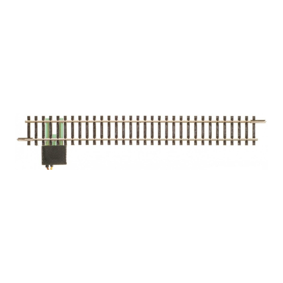
Gerades Anschlussgleis, analog
Voie de raccordement droite, analogique Rovná napájecí kolej, analogová Prosty tor przyłączowy, analogowy
Art.-Nr. / Item no. / Réf. / Art.- č . / Nr art.: 83143
(DE) Das gerade Anschlussgleis des TT-Mo-
analogique. Ne pas utiliser en fonctionnement
dell-Gleissystems, das eine Länge von 166 mm
numérique. En fonctionnement numérique, utili-
aufweist, ist ausschließlich nur für analogen
ser la voie de raccordement art. n° 83149.
Fahrbetrieb geeignet. Bitte nicht für Digitalbe-
(CZ) Rovná přípojná kolej modelového kolejiště
trieb verwenden! Bei Digitalbetrieb benutzen Sie
systému TT o délce 166 mm je vhodná výlučně
bitte das Anschlussgleis mit der Art.-Nr. 83149.
pro
digitální provoz! Pro digitální provoz použijte
(GB) The straight siding of the TT model track
napájecí kolej s obj.č. 83149.
system, which has a length of 166 mm, is only
suitable for analogue operation. Please do not
(PL) Prosty tor przyłączowy systemu torowe-
use it for digital operation! For digital operation,
go modeli TT, o długości 166 mm, nadaje się
please use the siding with article no. 83149.
wyłącznie do analogowego trybu jezdnego. Pro-
simy nie stosować go do trybu cyfrowego! Do
(FR) La voie de raccordement droite du systè-
trybu cyfrowego należy używać toru przyłączo-
me TT, qui possède une longueur de 166 mm,
est prévue uniquement pour un fonctionnement
wego o nr art. 83149.
Verwendbarkeit / Usability / Utilisation pratique / Použitelnost / Przydatność
Die Leiterplatte ist für folgende Artikel, die mit "A" gekennzeichnet sind, verwendbar:
(GB) The circuit board can be used for the following articles marked with „A":
(FR) Le circuit imprimé est utilisable pour les articles suivants marqués d'un „A":
(CZ) Desku s plošnými spoji lze použít pro komponenty označené písmenem „A":
(PL) Płytkę drukowaną można stosować dla następujących artykułów,
oznaczonych "A":
Gerades Gleis, 166 mm / (GB) Straight track, 166 mm
(FR) Voie droite, 166 mm / (CZ) Rovná kolej, 166 mm / (PL) Prosty tor, 166 mm
Gerades Gleis, 83 mm / (GB) Straight track, 83 mm / (FR) Voie droite, 83 mm
(CZ) Rovná kolej, 83 mm / (PL) Prosty tor, 83 mm
Gebogenes Gleis R 310 mm / (GB) Curved track R 310 mm / (FR) Voie courbe
R 310 mm / (CZ) Oblouková kolej R 310 mm / (PL) Wygięty tor R 310 mm
Gebogenes Gleis R 353 mm / (GB) Curved track R 353 mm
(FR) Voie courbe R 353 mm / (CZ) Oblouková kolej R 353 mm
(PL) Wygięty tor R 353 mm
Gebogenes Gleis R 396 mm / (GB) Curved track R 396 mm
(FR) Voie courbe R 396 mm / (CZ) Oblouková kolej R 396 mm
(PL) Wygięty tor R 396 mm
Gerades Schwellenband / (GB) Straight sleeper band
(FR) Bande de traverses droite / (CZ) Rovný pás pražců
(PL) Prosta wstęga podkładów
Gebogenes Schwellenband / (GB) Curved sleeper band
(FR) Bande de traverses courbe / (CZ) Obloukový pás pražců
(PL) Wygięta wstęga podkładów
Gebogenes Schwellenband / (GB) Curved sleeper band
(FR) Bande de traverses courbe / (CZ) Obloukový pás pražců
(PL) Wygięta wstęga podkładów
Gebogenes Schwellenband / (GB) Curved sleeper band
(FR) Bande de traverses courbe / (CZ) Obloukový pás pražců
(PL) Wygięta wstęga podkładów
www.tillig.com / www.facebook.com/tilligbahn
analogový
provoz.
Nepoužívejte
pro
Art.-Nr.
Item no.
Réf.
Art.-č.
Nr art.
83101
83102
83109
83106
83111
83001
83006
83008
83011
Straight siding, analogue
Montage / Assembly / Montage / Montáž / Montaž
(DE) Die Anschlussleiterplatte ist nicht fest mit dem Profil verbun-
den. Sie wird in die dafür vorgesehenen Aussparungen zwischen
Schwellenband und Schienenprofil eingeschoben. Das ist von
beiden Seiten des Gleises möglich. Das Schwellenband ist auf
der Unterseite mit "A" gekennzeichnet.
1. Anschlußleiterplatte zwischen Profil und Schwellenband
(zwischen 3.+4. sowie 5.+6. Schwelle) einschieben.
2. Kabel an Leiterplatte anstecken.
3. Abdeckung mit vorgesehenen Nuten auf die Leiterplatte
aufschieben.
4. Abbildung des fertig montierten Anschlußgleises.
(GB) The connection circuit board is not firmly connected to the
profile. It is inserted into the recesses provided for this purpose
between sleeper band and rail profile. It is possible from both
sides of the track. The sleeper band is marked with „A" on the
underside.
1. Insert the connection circuit board between profile
and the sleeper band (between 3rd+4th and 5th+6th
band).
2. Connect cable to circuit board.
3. Push the cover with grooves provided onto the prin-
ted circuit board.
4. Illustration of the completely mounted siding.
(FR) Le circuit imprimé de raccordement n'est pas attaché de
manière fixe au profil. Il est inséré dans les engagements prévus
entre bande de traverses et profil de voie. Ce qui est possible
d'un côté ou de l'autre de la voie. La bande de traverses est
marquée d'un „A" sur le dessous.
Kabel
Kabel
Kabel
Cable
Leiterplatte
Câble
Circuit board
Carte de circuits imprimés
2
Deska s plošnými spoji
Płytka drukowana
3
Abdeckung
2
Leiter-
1
Abdeckung
platte
Abdeckung / Cover
Leiter-
1
Couverture
platte
Kryt / Osłona
2 4 6
Schwelle 1 3 5 7...
2 4 6
Schwelle 1 3 5 7...
Schwelle
Sleeper / Traverse / Pražec / Podkład
1. Circuit imprimé de raccordement à insérer entre profil
et bande de traverses (entre 3e+4e et 5e+6e traverses).
2. Relier le câble au circuit imprimé.
3. Glisser le couvercle sur le circuit imprimé dans les
rainures prévues à cet effet.
4. Représentation de la voie de raccordement une fois
montée.
(CZ) Připojovací deska není pevně spojena s profilem. Vkládá
se do příslušných vybrání pásem pražců a profilem kolejnice. To
je možné z obou stran koleje. Pás pražců je na spodní straně
označen písmenem „A".
1. Připojovací desku zasuňte mezi profil a pás pražců
(mezi 3.+4. a 5.+6 pražec).
2. Připojte kabel k připojovací desce.
3. Nasaďte kryt pomocí drážek na připojovací desku.
4. Vyobrazení hotové smontované napájecí koleje.
(PL) Przyłączowa płytka drukowana nie jest połączona z profilem
na stałe. Wsuwa się ją w przewidziane do tego celu wgłębienia
między wstęgą podkładów a profilem szyny. Jest to możliwe z
obu stron toru. Wstęga podkładów jest oznaczona na spodzie
literką "A".
1. Wsunąć drukowaną płytkę przyłączową między profil
i wstęgę podkładów (między 3.+4. oraz 5.+6. podkład).
2. Podłączyć kable do płytki drukowanej.
3. Wsunąć osłonę na płytkę drukowaną w przewidziane
do tego celu wpusty.
4. Ilustracja zmontowanego toru przyłączowego.
3
Gerades Gleis
Straight track
Voie droite
Gerades Gleis
Rovná kolej
Gerades Gleis
Auch von dieser Seite ist das Auf-
Prosty tor
(DE) Auch von dieser Seite ist das Auf-
schieben der Leiterplatte möglich.
schieben der Leiterplatte möglich.
Auch von dieser Seite ist das Auf-
(GB) The printed circuit board can also be pushed on from this side.
schieben der Leiterplatte möglich.
(FR) Le circuit imprimé peut également être inséré de ce côté.
(CZ) Nasunutí desky tištěného spoje je možné taky z této strany.
(PL) Nasunięcie płytki drukowanej możliwe jest także z tej strony.
4
4
368420 / 04.05.2020
Advertisement

Related Manuals for TILLIG BAHN 83143


Summary of Contents for TILLIG BAHN 83143
- Page 1 Straight siding, analogue Voie de raccordement droite, analogique Rovná napájecí kolej, analogová Prosty tor przyłączowy, analogowy Art.-Nr. / Item no. / Réf. / Art.- č . / Nr art.: 83143 Montage / Assembly / Montage / Montáž / Montaž...
- Page 2 TILLIG Modellbahnen GmbH Promenade 1, 01855 Sebnitz Tel.: +49 (0)35971 / 903-45 • Fax: +49 (0)35971 / 903-19 (DE) Hotline Kundendienst • (GB) Hotline customer service • (FR) Services à la clientèle Hotline (CZ) Hotline Zákaznické služby • (PL) Biuro Obsługi Klienta: www.tillig.com/Service_Hotline.html (DE) Technische Änderungen vorbehalten! Bei Reklamationen wenden Sie sich bitte an Ihren Fachhändler.
Need help?
Do you have a question about the 83143 and is the answer not in the manual?
Questions and answers